TR7007M_SII_Hardware_en_v1-0-1.pdf - 第29页
Test Research, Inc. TR7007M SII User Guide – Hardware 19 Figure 50 : Output(Y) Values Y10 0 - Y1 0F Figure 51 : Output(Y) Values Y11 0 - Y1 1F Figure 52 : Output(Y) Values Y12 0 - Y1 2F P C & PLC I/O: Use this func…
Test Research, Inc.
18 TR7007M SII User Guide – Hardware
Figure 46: Light Display
3.2.4 I/O Display
From the options in Figure 47
, [INPUT(X)], [OUTPUT(Y)], [STEP(S)] and [INLINE] can be
selected to monitor the execution status of the PLC program.
Figure 47: I/O Display
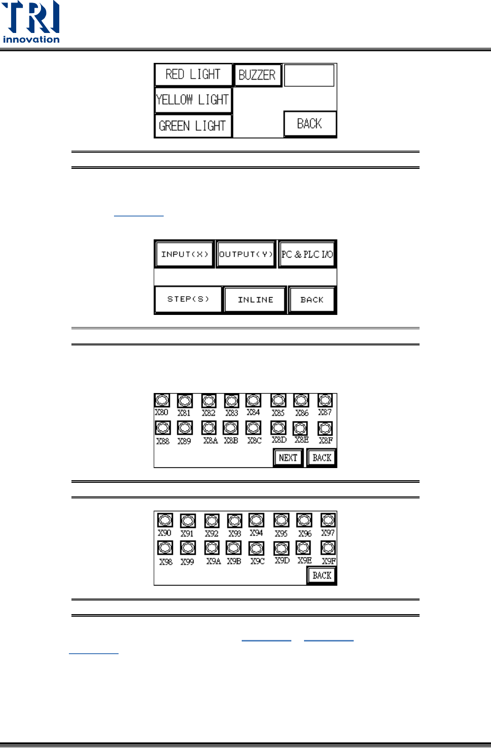
INPUT(X): The X80~X9F values from Figure 48 and Figure 49 can be compared against
Figure 56 to monitor the PLC to see if the input points are normal.
Figure 48: Input(X) Values X80-X8F
Figure 49: Input(X) Values X90-X9F
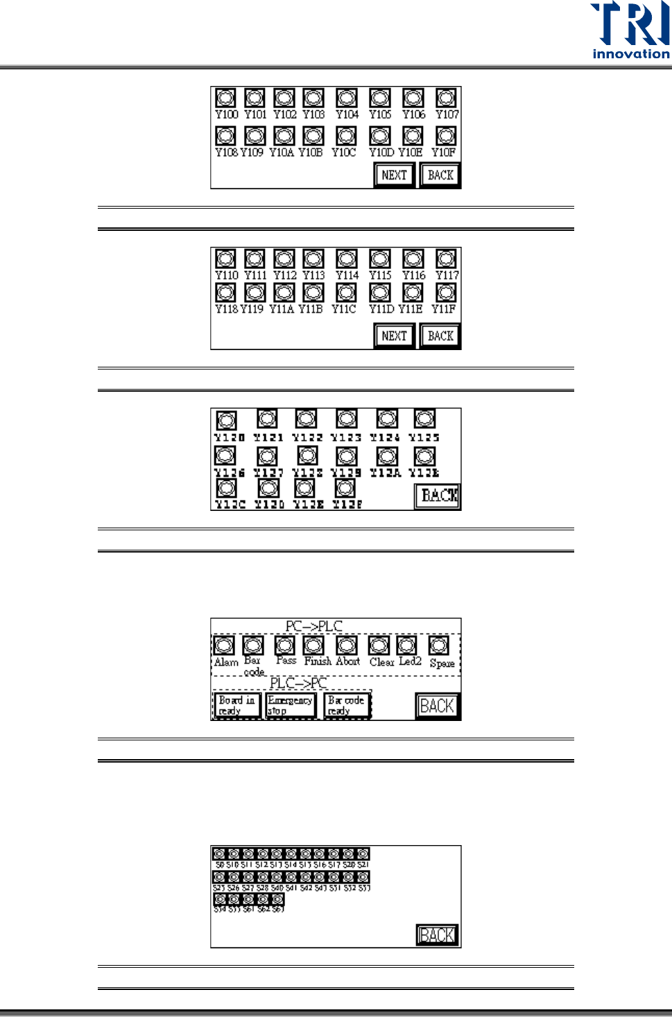
OUTPUT(Y): The Y100~Y120 values from Figure 50 ~ Figure 52 can be compared
against Figure 56 to monitor the PLC to see if the output points are normal.
Test Research, Inc.
TR7007M SII User Guide – Hardware 19
Figure 50: Output(Y) Values Y100-Y10F
Figure 51: Output(Y) Values Y110-Y11F
Figure 52: Output(Y) Values Y120-Y12F
PC & PLC I/O: Use this function in coordination with the I/O testing function in the main
program to review the Input and Output signals.
Figure 53: PC & PLC I/O
STEP(S): When step by step operation is selected, the step at which the system’s
operation experiences a problem can be identified; this is shown during system Reset,
Bypass and normal operations.
Figure 54: Stepping
Test Research, Inc.
20 TR7007M SII User Guide – Hardware
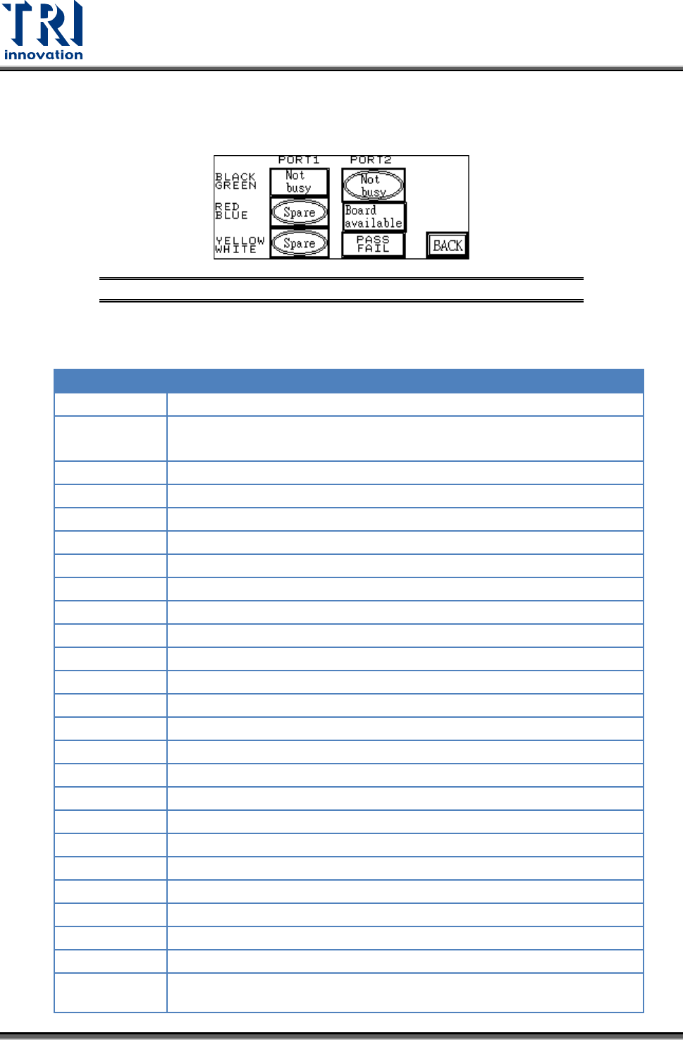
INLINE: Port1 and Port2 can be used to perform a self-diagnostic check. Connect the
Port1 and Port2 connectors that have the same color and at Figure 55 press [Not busy],
[Board available] or [PASS FAIL] to see if the corresponding input is shown.
Figure 55: I/O Display – INLINE Option
The following table lists the Input/Output signals for the X-Y table
PIN NUMBER
PIN DIFN.
X80(IN)
EMS
X87(IN)
DRCH RESET DONE(used by TR7100)
X8A(IN)
Loader board ready signal for barcode pre-read function
X90(IN)
SENSOR1
X91(IN)
SENSOR2
X92(IN)
SENSOR3
X93(IN)
SENSOR4
X94(IN)
SENSOR5
X95(IN)
SENSOR6
X98(IN)
UNLOADER READY (from load - port2 Black-Green)
X9A(IN)
TEST OK (from pc)
X9B(IN)
PC TEST COMPLETE (from pc)
X9C(IN)
PC ABORT (from pc)
X9D(IN)
CLEAR NOTIFY PC TEST (from pc)
X9E(IN)
2D LED2(from PC, used by the TR7006/L)
X9F(IN)
LASER ON(from PC, used by the TR7006/L)
Y100(OUT)
RED LIGHT
Y101(OUT)
YELLOW LIGHT
Y102(OUT)
GREEN LIGHT
Y103(OUT)
BUZZER
Y104(OUT)
REQUEST BOARD FROM LOADER (to unload – Port1 Black-Green)
Y105(OUT)
TEST OK (to unload - port1 Yellow-White)
Y109(OUT)
BARCODE START
Y110(OUT)
START CONVEYOR MOTOR (used by TR7100)
Y111(OUT)
STOP CONVEYOR MOTOR (used by TR7100)
Y112(OUT)
SLOW CONVEYOR MOTOR (used by TR7100),
2D LED2 (used by TR7600/L)