TR7007M_SII_Hardware_en_v1-0-1.pdf - 第44页
Test Research, Inc. 34 TR7007 M SII User Guide – Hardware Figure 83 : Loader and Unloader Socket Positi on Figure 84 : Loader and Unloader Cabl e 4.3.2 Unloader Connection PO RT2 – DOWN LINE X98 Black (1) / G reen (2) Re…
Test Research, Inc.
TR7007M SII User Guide – Hardware 33
4 CONVEYOR
4.1 Architecture and Function
The main function of the conveyor belt is to transport a PCB or a multi-board panel and
complete the loading/unloading operation. Long term operation may lead to the conveyor belt
not being fully set on the drive axle, so users are advised to check that the front and back
conveyor belts are set properly on their axles before beginning operations. If the belt needs
to be replaced, first fit the belt on to the drive axles on both ends before fitting it in order over
the inner axles.
4.2 Sensor Adjustment and Replacement
1) Sensors 1 & 4 (Loading/Unloading Sensors): Use the adjustment rod to adjust the Sensor
sensitivity until the indicator light is lit. (If there is an obstruction over the Sensor, the
indicator light will be lit, if there is no obstruction over the Sensor, the indicator will be off.)
Then gradually reduce it until the indicator light goes off. This will be the optimal sensor
status for Loading/Unloading.
2) Sensors 2 & 3 (Brake and Stop Sensors): Adjustment method is the same as above, but
the LED light base must be moved into position above the Sensor to check if the LED
light base will interfere, causing faulty operation. If interference does occur, the Sensor’s
sensitivity needs to be reduced until it is no longer affected by the LED light socket but
still able to sense the candidate board.
3) Sensors 5 & 6: (Holder Motor Sensors): Lower the holder mechanism to its lowest
position along with the Sensor. Move the Sensor upwards until the indicator light is lit,
then move it slowly downwards again until the indicator light goes off for the correct
setting.
4) Replacement: If a Sensor is not working, then the Sensor’s sensitivity should be re-
adjusted. If it still does not operate, replace with a new sensor. Replacement Method: first
disconnect the Sensor connector, and then remove the Sensor. Attach the new Sensor
then connect and secure the Sensor’s connectors. Once replacement is complete, adjust
as directed in the relevant adjustment method.
4.3 Linking with Loader and Unloader
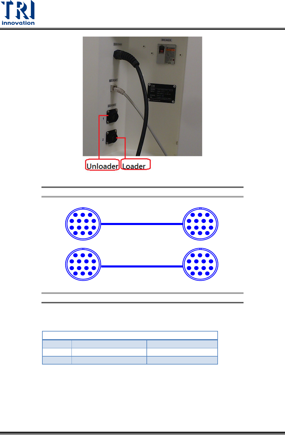
4.3.1 Loader Connection
PORT1 – UP LINE
Y104
Black (1) / Green (2)
Ready
X8A
Red (3) / Blue (4)
Board Available
X8B
Yellow (5) / White (6)
Spare
Located below the power supply socket in the back of the equipment is I/O PORT1. Connect
the connector, and there are three sets of different colored wire pairs at the connector end.
These are: Black-Green (Y104) for requesting board from Loader, Red-Blue (X8A) reserved
INPUT connector and the Yellow-White (X8B) reserved INPUT connector. Connect the
Black-Green connector to the Loader Board Request connection. (We use the standard
SMEMA signal. If this is different due to differences in manufacturer, contact the front stage
manufacturer to acquire the connection data.)
Test Research, Inc.
34 TR7007M SII User Guide – Hardware
Figure 83: Loader and Unloader Socket Position
Figure 84: Loader and Unloader Cable
4.3.2 Unloader Connection
PORT2 – DOWN LINE
X98
Black (1) / Green (2)
Ready
Y106
Red (3) / Blue (4)
Board Available
Y105
Yellow (5) / White (6)
OK: Short; NG: Open
Located below the power supply socket in the back of the equipment is I/O PORT2. Connect
the connector, and there are three sets of different colored wire pairs at the connector end.
These are: Black-Green (X98) for receiving READY board request signal from the Unloader,
Red-Blue (Y106) board unload signal to the Unloader and the Yellow-White (Y105) TEST
PASS signal connector. Connect the Black-Green connector with the Unloader’s connector
for sending READY board request signal. Then connect the Yellow-White connector with the
Unloader TEST PASS signal receiving signal. (We use the standard SMEMA signal. If this is
PIN1~PIN6
1 2 3
4 5 6 7
8 9 10 11
12 13 14
PIN1~PIN6
1 2 3
4 5 6 7
8 9 10 11
12 13 14
1 2 3
4 5 6 7
8 9 10 11
12 13 14
1 2 3
4 5 6 7
8 9 10 11
12 13 14
Test Research, Inc.
TR7007M SII User Guide – Hardware 35
different due to differences in manufacturer, contact the front stage manufacturer to acquire
the connection data.)
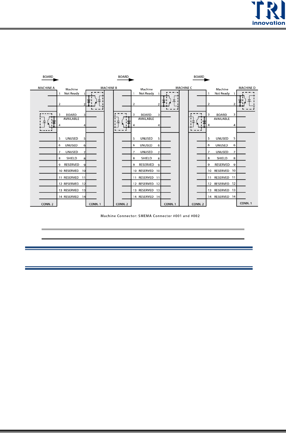
The standard SMEMA signal link scheme is shown in the figure below.
Figure 85: Standard SMEMA signal link
NOTE: The above connections are all single point relays so there are no
positive or negative polarity differences.