TR7007M_SII_Hardware_en_v1-0-1.pdf - 第39页
Test Research, Inc. TR7007M SII User Guide – Hardware 29 5) Aft er backup, close the o riginal PLC program. Then click on File to Open the PLC interface program (*.fp) you w ish to updat e as sho wn in the figure below. …
Test Research, Inc.
28 TR7007M SII User Guide – Hardware
3.5 PLC Program Replacement
1) First connect the PLC-PC data cable properly, with the PS2 connector connected to the
rear of the PCI, and the RS232 connected to Main PC COM1.
2) Open the Program Files and select FPWIN GR.
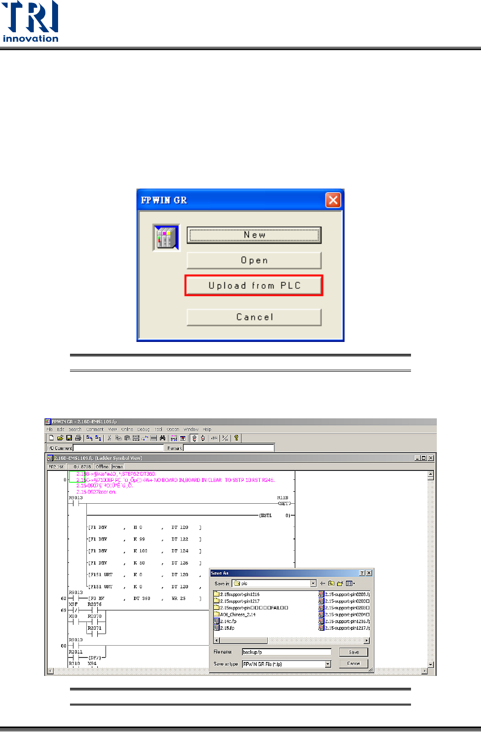
3) Enter the [FPWIN GR] software program and click on [Upload from PLC] as shown in the
figure below.
Figure 74: FPWIN-GR – Select Upload from PLC
4) After uploading, click on [File] and select [Save] to make a backup of the original files as
shown in the figure below:
Figure 75: FPWIN-GR – Backup Original Files
Test Research, Inc.
TR7007M SII User Guide – Hardware 29
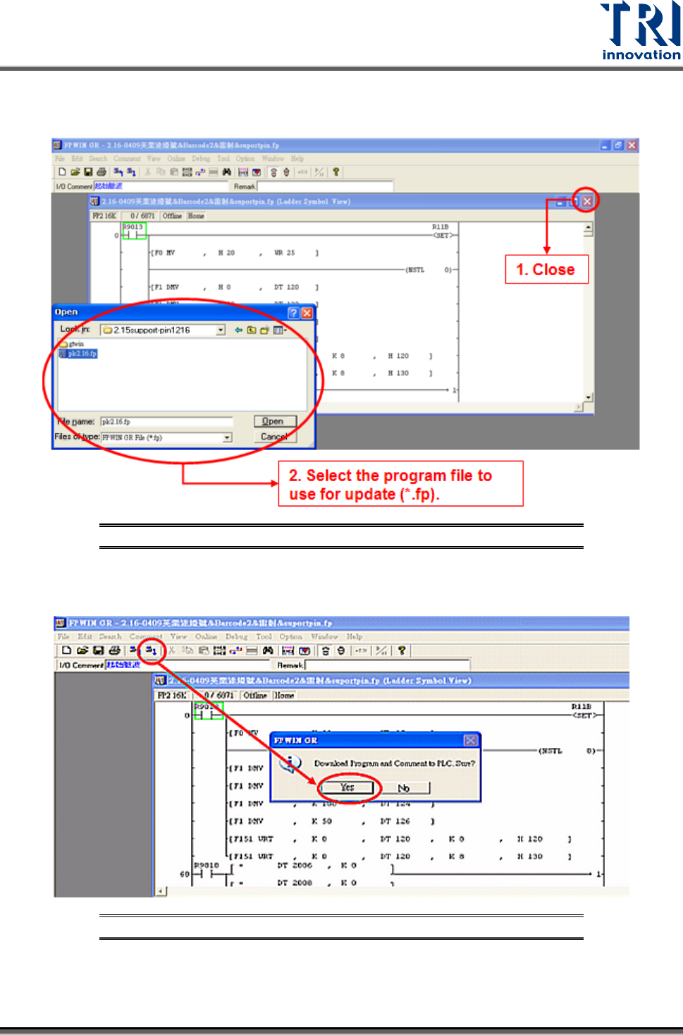
5) After backup, close the original PLC program. Then click on File to Open the PLC
interface program (*.fp) you wish to update as shown in the figure below.
Figure 76: FPWIN-GR – Select Update Program
6) Click on the icon in the menu [Download to PLC], click [Yes] to confirm overwrite of
existing program as shown in the picture below:
Figure 77: FPWIN-GR – Confirm Overwrite
7) Wait for the PC to transfer the data to the PLC, and the program will be updated.
Test Research, Inc.
30 TR7007M SII User Guide – Hardware
3.6 PLC Hardware Overview
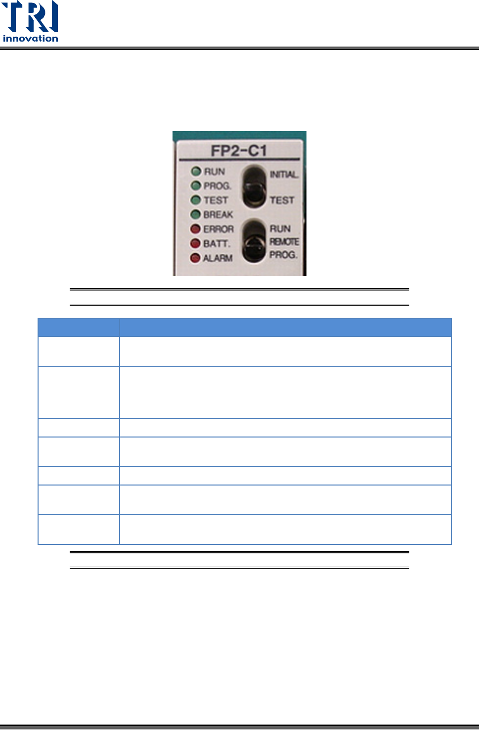
3.6.1 CPU (FP2-C1)
Status Indicator LEDs
Figure 78: PLC’s CPU LEDs & Switches
LED
DESCRIPTION
RUN (green)
This is lit in the RUN mode, to indicate that the program is being
executed. It flashes during forced input/output.
PROG. (green)
This is lit in the PROG. mode. Operation stops while this LED is lit. It
flashes when waiting for connection of slave station on remote I/O
system. If the memory is initialized, the brightness dims, indicating that
initialization is being executed.
TEST (green)
This si lit in the test operation mode.
BREAK (green)
This is lit in the operation halts at a break during a test run or halts during
the step operation mode for the test run.
ERROR (red)
This is lit if an error is detected during the self-diagnostic function.
BATT. (red)
This is lit when the voltage of the backup battery drops below a specific
value.
ALARM (red)
This is lit if a hardware error occurs, or if operation slows because of the
program, and the watchdog timer is activated.
Figure 79: CPU(FP2-C1) – Status Indicator LEDs