TR7007M_SII_Hardware_en_v1-0-1.pdf - 第28页
Test Research, Inc. 18 TR7007 M SII User Guide – Hardware Figure 46 : Light Display 3.2.4 I/O D isplay From the options in F igure 47 , [ INPUT(X) ] , [ OUTPUT(Y) ] , [ STEP(S) ] and [ INLINE ] can be selected to monitor…
Test Research, Inc.
TR7007M SII User Guide – Hardware 17
Figure 43: DEBUG Display
3.2.1 CONV.
Press [FORWARD] or [REVERSE] and the Conveyor belt will immediately run forwards or in
reverse and jump to the display shown in Figure 45
. Press [STOP] and the conveyor belt will
immediately stop and jump back to the display shown in Figure 44; press [BACK] to return to
Figure 43: DEBUG Display.
Figure 44: Forward/Reverse Settings for Conveyor Belt
Figure 45: Stop Conveyor Belt
3.2.2 CONV. WIDTH
Press the [CONV. WIDTH] in Figure 43: DEBUG Display and
Figure 8: Auto/Manual
Conveyor Adjust will appear. Use the spin wheel to set the conveyor width, and when the
setting is completed press BACK. The system will lock the CONV. WIDTH adjustment
function and return to
Figure 43: DEBUG Display.
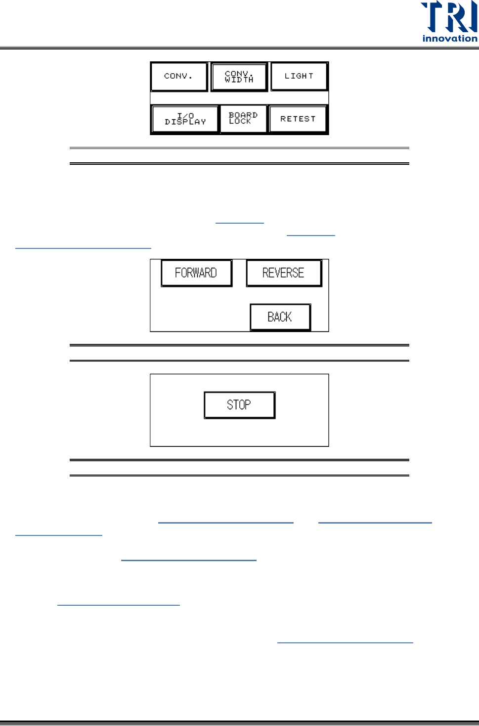
3.2.3 LIGHT
Refer to Figure 46: Light Display
. Press [RED LIGHT], [YELLOW LIGHT], [GREEN LIGHT]
or [BUZZER] to test that each is operating correctly. When a light button is pressed, the
corresponding light on the signal tower should light. When the buzzer button is pressed, the
alarm buzzer should sound. Press [BACK] to return to
Figure 43: DEBUG Display.
Test Research, Inc.
18 TR7007M SII User Guide – Hardware
Figure 46: Light Display
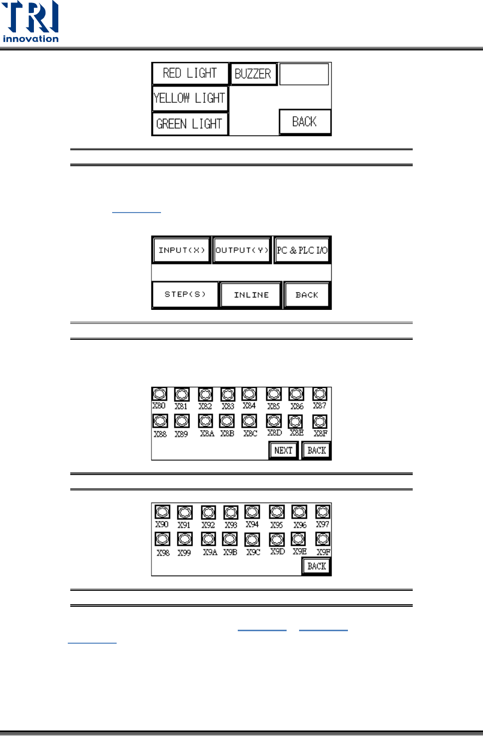
3.2.4 I/O Display
From the options in Figure 47
, [INPUT(X)], [OUTPUT(Y)], [STEP(S)] and [INLINE] can be
selected to monitor the execution status of the PLC program.
Figure 47: I/O Display
INPUT(X): The X80~X9F values from Figure 48 and Figure 49 can be compared against
Figure 56 to monitor the PLC to see if the input points are normal.
Figure 48: Input(X) Values X80-X8F
Figure 49: Input(X) Values X90-X9F
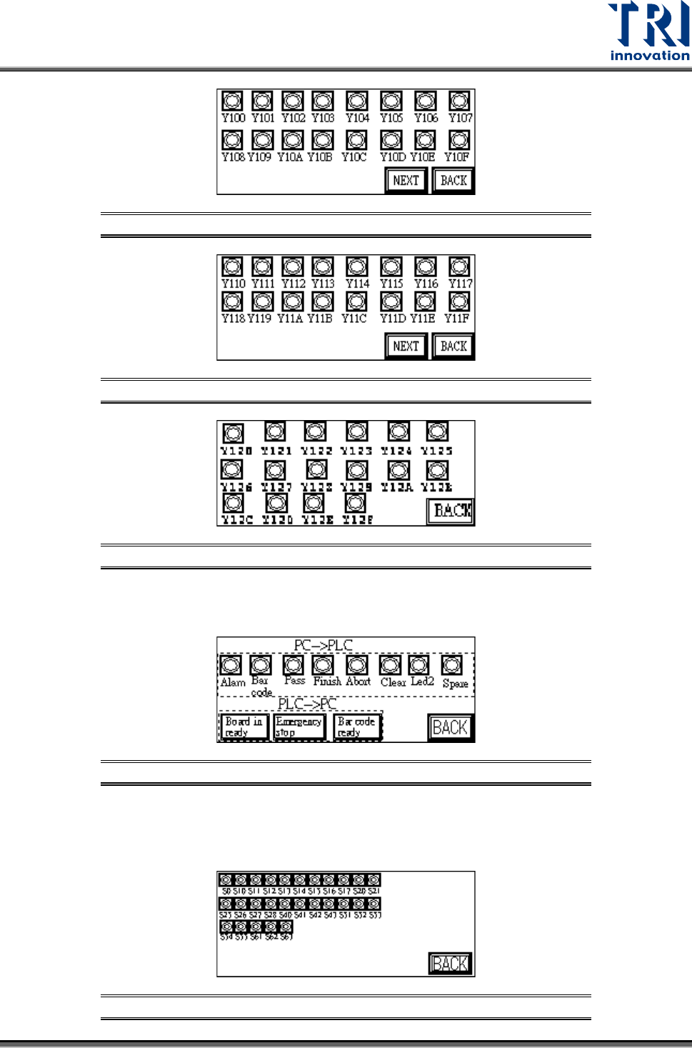
OUTPUT(Y): The Y100~Y120 values from Figure 50 ~ Figure 52 can be compared
against Figure 56 to monitor the PLC to see if the output points are normal.
Test Research, Inc.
TR7007M SII User Guide – Hardware 19
Figure 50: Output(Y) Values Y100-Y10F
Figure 51: Output(Y) Values Y110-Y11F
Figure 52: Output(Y) Values Y120-Y12F
PC & PLC I/O: Use this function in coordination with the I/O testing function in the main
program to review the Input and Output signals.
Figure 53: PC & PLC I/O
STEP(S): When step by step operation is selected, the step at which the system’s
operation experiences a problem can be identified; this is shown during system Reset,
Bypass and normal operations.
Figure 54: Stepping