TR7007M_SII_Hardware_en_v1-0-1.pdf - 第33页
Test Research, Inc. TR7007M SII User Guide – Hardware 23 1) SENSO R Always On: The S ensor sensitivity range is too long. The candidate board has been covering the sens or for too long, there may be a jam or the conv…
Test Research, Inc.
22 TR7007M SII User Guide – Hardware
Figure 59: Confirm to Open the Support Pin Function
3.2.6 Reset
Press [Reset] to return to the standby screen (Figure 37, Figure 38, or Figure 39
).
3.3 HCI Alert Messages and Causes
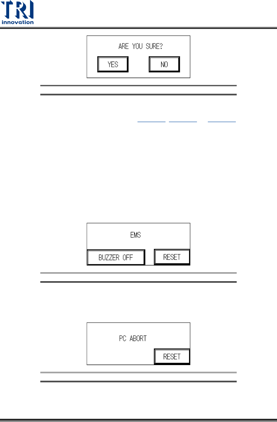
3.3.1 EMS
User can press [BUZZER OFF] to turn off the buzzer and check the machine. After
troubleshooting, user can press [RESET] to return to the Standby screen. If the
troubleshooting is not finished and user still presses [RESET], the screen will go back to the
EMERGENCY STOP screen again. The possible causes are:
1) The emergency stop button has been pressed.
2) The front door or rear door has been opened. To deactivate this function, set the interlock
switch on the inside of the front door to OFF. Please pay attention to safety
Figure 60: Emergency Stop Display
3.3.2 PC Abort
PC sends the ABORT message, then user has to check if the link between PC and PLC is
normal.
Figure 61: PC Abort Display
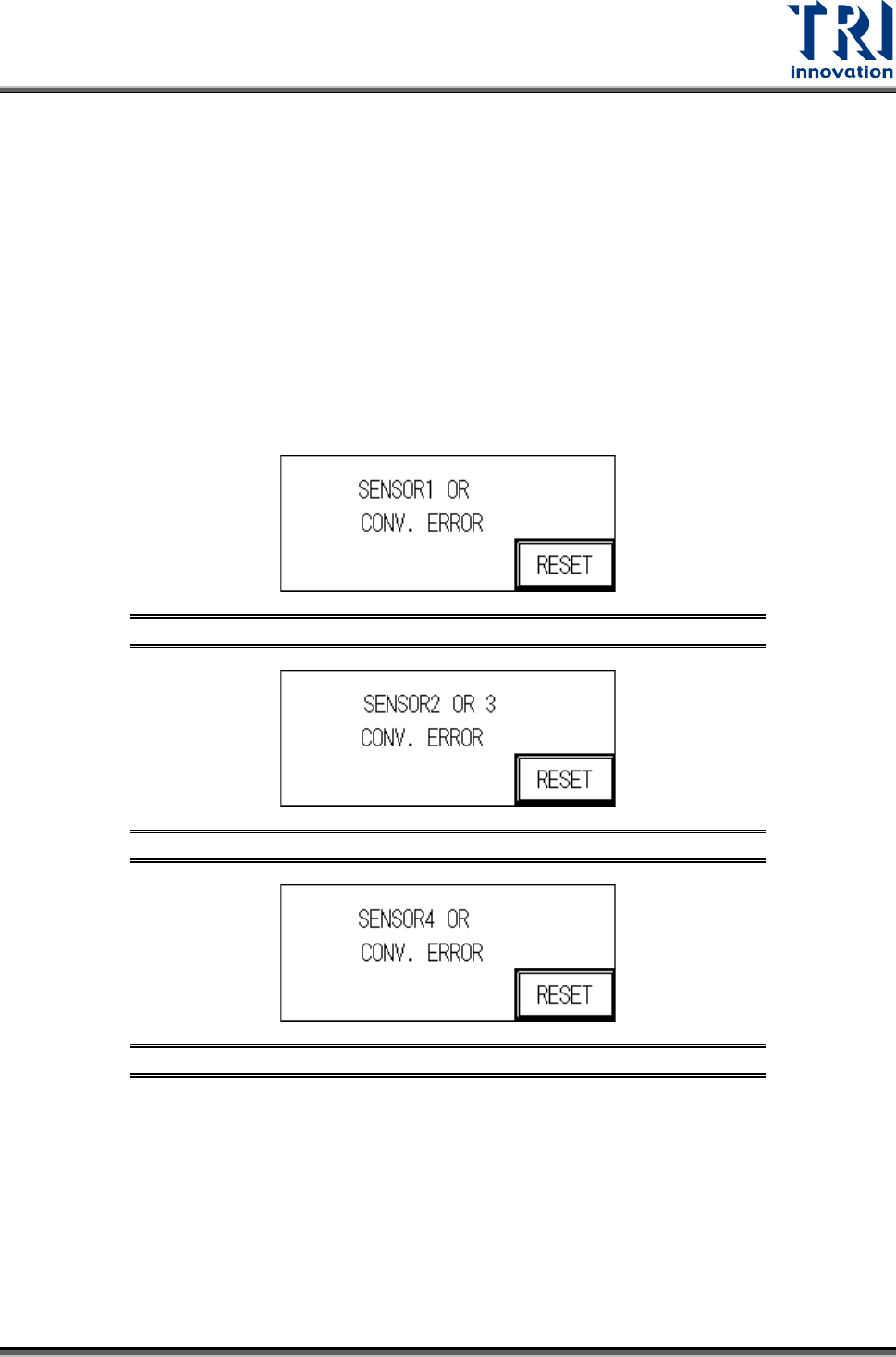
3.3.3 Sensor or Conv. Error
The reasons for a Sensor or Conv. Error may be:
Test Research, Inc.
TR7007M SII User Guide – Hardware 23
1) SENSOR Always On:
The Sensor sensitivity range is too long.
The candidate board has been covering the sensor for too long, there may be a jam or the
conveyor belt may not be operating.
2) SENSOR Always OFF:
The Sensor sensitivity range is too short.
The candidate board has not been detected by the sensor for too long, there may be a
jam or the conveyor belt may not be operating.
3) Conveyor Error: Motor or Motor Driver Malfunctioning, or Belt Detached.
Figure 62: Sensor 1 Error
Figure 63: Sensor 2 or 3 Error
Figure 64: Sensor 4 Error
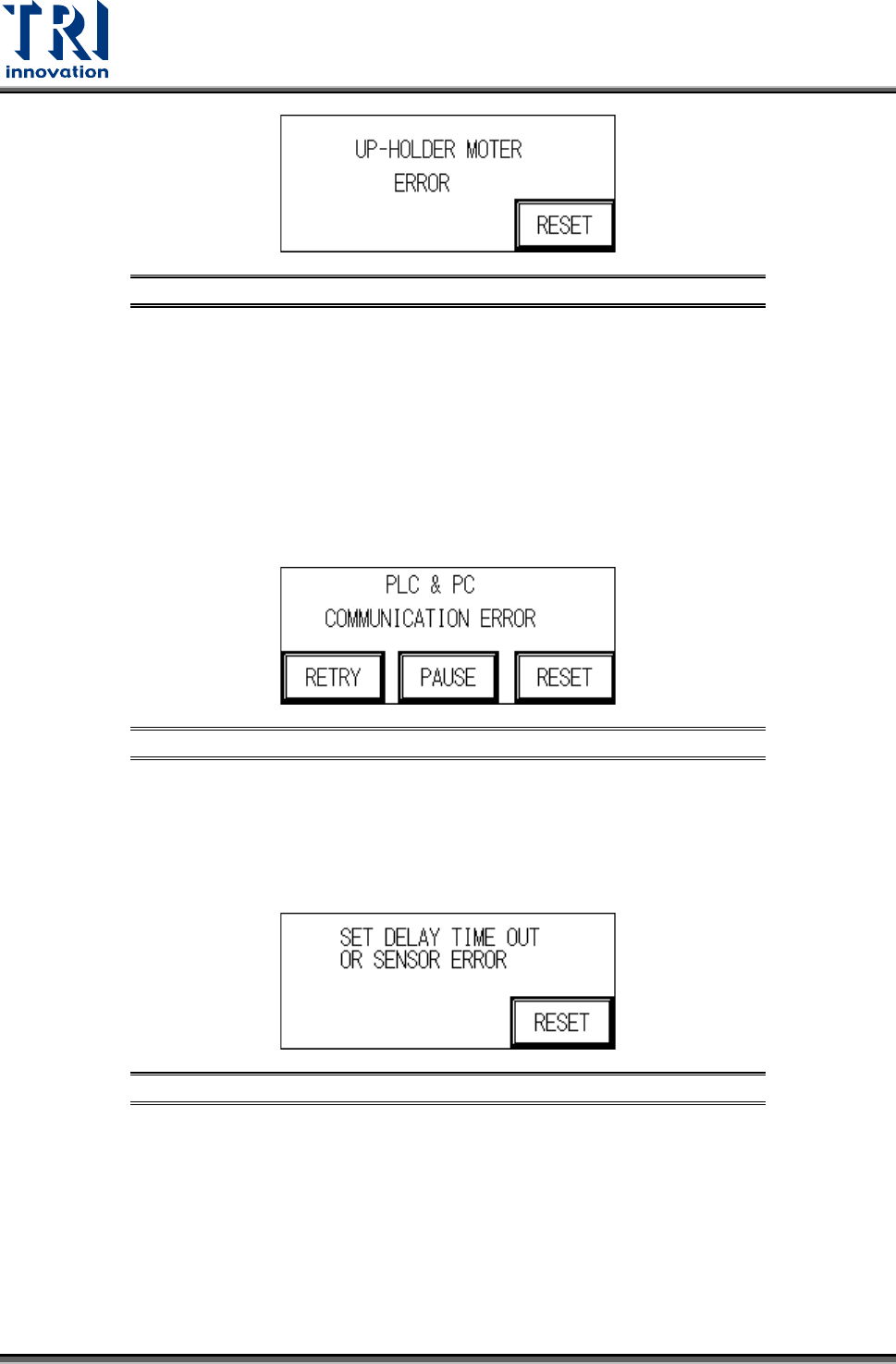
3.3.4 UP-Holder Motor Error
The reasons for a Holder Motor Error may be:
1) Sensor 5 or 6, ON/OFF error: Incorrect detection height adjustment.
2) Motor Error: Motor or Motor Driver malfunction.
Test Research, Inc.
24 TR7007M SII User Guide – Hardware
Figure 65: Up-Holder Motor Error
3.3.5 PC & PLC Communication Error
The candidate board has been locked and the PC notified to commence testing. No action
taken within 10 seconds of the notification. After troubleshooting, user can press [RETRY] to
inspect the board again or press [PAUSE] to turn off the alarm sound or press [RESET] to
return to standby screen.
1) PC & PLC communication link malfunction.
2) PC program not being executed or malfunctioning.
Figure 66: PC & PLC Communication Error
3.3.6 Set Delay Time Out or Sensor Error
When the loading speed is too fast or Sensor 1 and Sensor 2 are located too closely
together, speed reduction may not occur in time so this measure is triggered to prevent
boards from falling off.
Figure 67: Speed Reduction Error
3.3.7 Test Fail
When the test results in a Fail, the PC will send a FAIL signal. A confirmation from the PC is
required before it can return to the system’s operational display.