TR7007M_SII_Hardware_en_v1-0-1.pdf - 第27页
Test Research, Inc. TR7007M SII User Guide – Hardware 17 Figure 43 : DEBUG Displ ay 3.2.1 CONV. Press [ F O RW A R D ] or [ REVERSE ] and the Conveyor belt w ill immediately run forwards or in reverse and j ump to the di…
Test Research, Inc.
16 TR7007M SII User Guide – Hardware
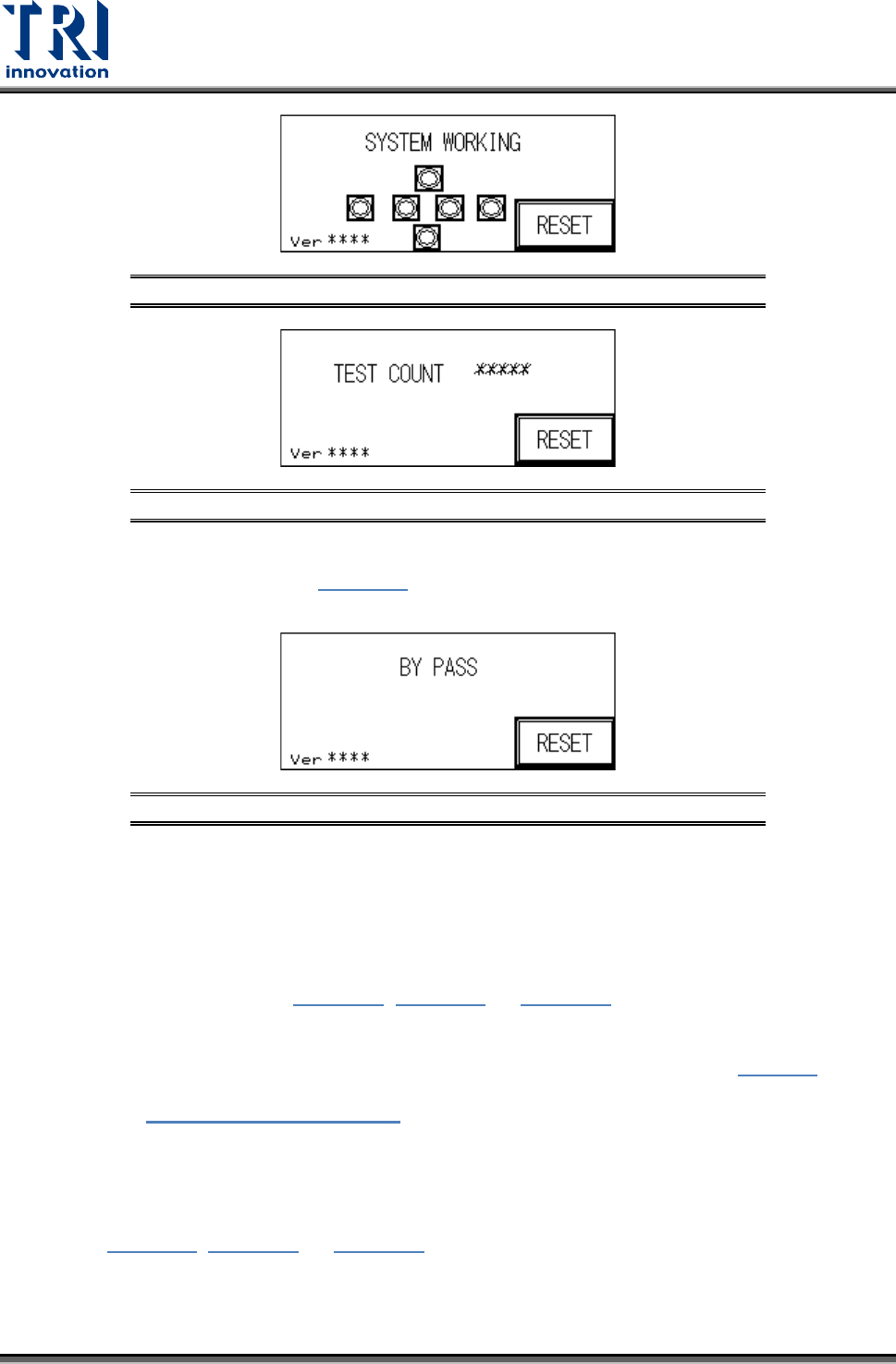
Figure 40: System Working Screen
Figure 41: Tests Performed
INLINE Mode: In Inline mode, if the system is malfunctioning or testing is not desired,
press [BYPASS] to show Figure 42
. The PCB will not be tested and go straight
through to the Unloader.
Figure 42: BYPASS Display
STAND-ALONE Mode: In Stand-Alone mode, if [CONTINUOUS TEST] is selected, 0.5
seconds after the tested board has been removed and 0.5 seconds after the next
board is inserted, automated loading and testing will run. If single [TEST] is selected,
when one board has been tested, then [TEST] must be pressed again to load the next
board for testing.
3) Hidden Button Setting: In Figure 37, Figure 38, or Figure 39
at the four corners of the
display there are four hidden buttons. These can be used to jump to the Startup page or
the Debug display. If the bottom left and right corner hidden buttons are pressed within
two seconds of each other, then it will jump to the Startup display shown in
Figure 3. If
the top left and right hidden buttons are pressed within two seconds of each other, then it
will open
Figure 43: DEBUG Display.
3.2 Debug Display
Refer to Figure 37, Figure 38, or Figure 39. If the hidden buttons in the upper-left and
upper- right corners are pushed and held for two seconds, the system will go to the Debug
screen shown in the following figure. In Debug screen, users can perform the tests described
in this section.
Test Research, Inc.
TR7007M SII User Guide – Hardware 17
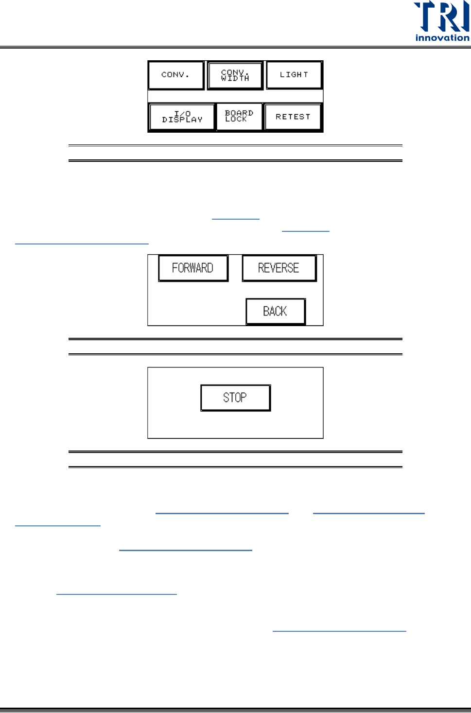
Figure 43: DEBUG Display
3.2.1 CONV.
Press [FORWARD] or [REVERSE] and the Conveyor belt will immediately run forwards or in
reverse and jump to the display shown in Figure 45
. Press [STOP] and the conveyor belt will
immediately stop and jump back to the display shown in Figure 44; press [BACK] to return to
Figure 43: DEBUG Display.
Figure 44: Forward/Reverse Settings for Conveyor Belt
Figure 45: Stop Conveyor Belt
3.2.2 CONV. WIDTH
Press the [CONV. WIDTH] in Figure 43: DEBUG Display and
Figure 8: Auto/Manual
Conveyor Adjust will appear. Use the spin wheel to set the conveyor width, and when the
setting is completed press BACK. The system will lock the CONV. WIDTH adjustment
function and return to
Figure 43: DEBUG Display.
3.2.3 LIGHT
Refer to Figure 46: Light Display
. Press [RED LIGHT], [YELLOW LIGHT], [GREEN LIGHT]
or [BUZZER] to test that each is operating correctly. When a light button is pressed, the
corresponding light on the signal tower should light. When the buzzer button is pressed, the
alarm buzzer should sound. Press [BACK] to return to
Figure 43: DEBUG Display.
Test Research, Inc.
18 TR7007M SII User Guide – Hardware
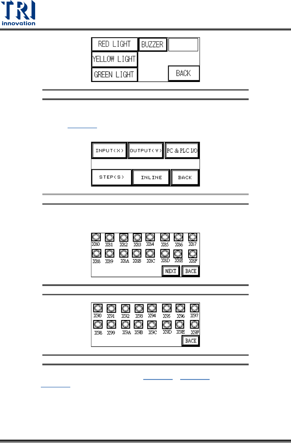
Figure 46: Light Display
3.2.4 I/O Display
From the options in Figure 47
, [INPUT(X)], [OUTPUT(Y)], [STEP(S)] and [INLINE] can be
selected to monitor the execution status of the PLC program.
Figure 47: I/O Display
INPUT(X): The X80~X9F values from Figure 48 and Figure 49 can be compared against
Figure 56 to monitor the PLC to see if the input points are normal.
Figure 48: Input(X) Values X80-X8F
Figure 49: Input(X) Values X90-X9F
OUTPUT(Y): The Y100~Y120 values from Figure 50 ~ Figure 52 can be compared
against Figure 56 to monitor the PLC to see if the output points are normal.