TR7007M_SII_Hardware_en_v1-0-1.pdf - 第25页
Test Research, Inc. TR7007M SII User Guide – Hardware 15 Figure 36 : Syst em Reset ting Screen Start TEST 1) Standby Screen: Once the system reset has been comple ted, if t he mode is set to Inline then the display w i…
Test Research, Inc.
14 TR7007M SII User Guide – Hardware
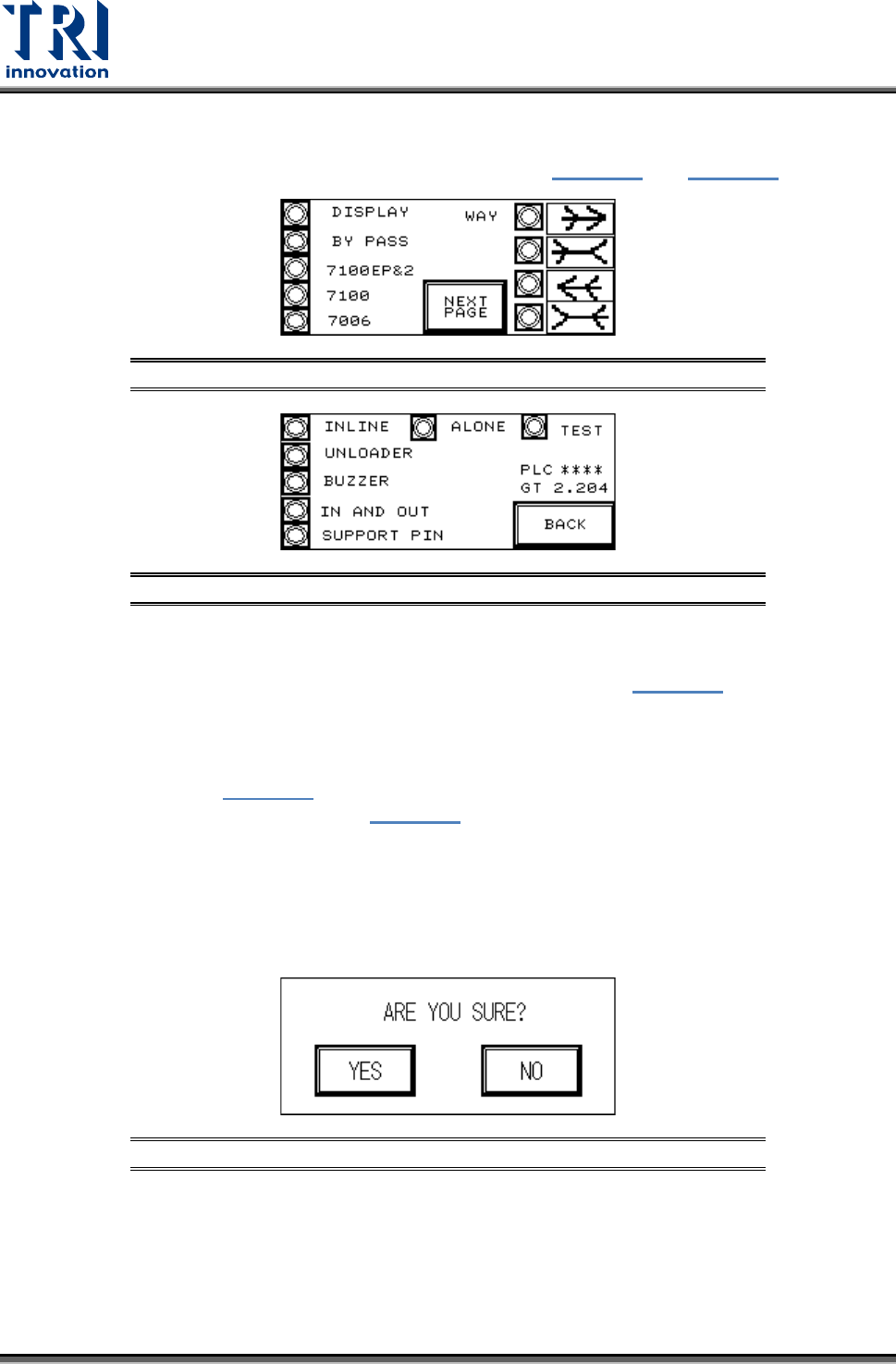
3.1.4 DISPLAY
All of the currently set mode parameters can be viewed in Figure 33 and Figure 34
.
Figure 33: Display Mode Parameters 1
Figure 34: Display Mode Parameters 2
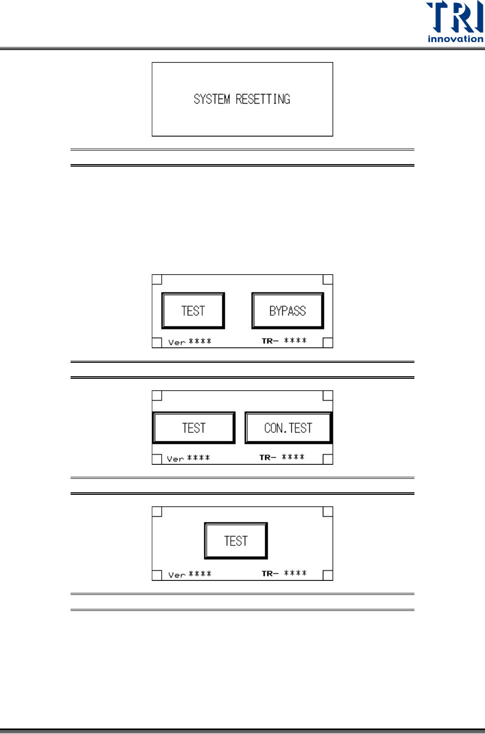
3.1.5 RESET
After pressing [RESET] the screen will show a confirmation dialog (Figure 35
). Once reset
has been completed testing will begin.
RESET Confirmation
If [YES] is pressed in Figure 35
then the Reset operation will be executed, and the display
will show that the system is resetting (Figure 36). If [NO] is pressed then it will return to the
previous display.
Upon the initial power up of the machine or after an emergency system shutdown, the Reset
action will return the X-Y Table to the original position and move the PCB to the unload end
(depending on the direction set). In other situations the X-Y Table will not move but the PCB
will still be moved to the unload end.
Figure 35: Confirm Reset Screen
Test Research, Inc.
TR7007M SII User Guide – Hardware 15
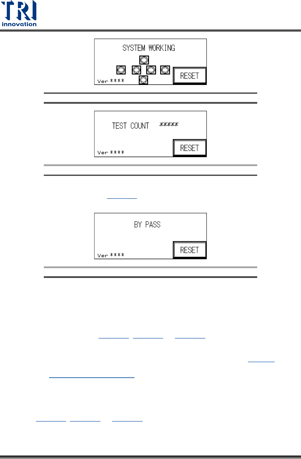
Figure 36: System Resetting Screen
Start TEST
1) Standby Screen: Once the system reset has been completed, if the mode is set to Inline
then the display will show two options: [TEST] and [BYPASS] (below). If the mode is set
to Stand-Alone mode then the display will show two options: single [TEST] and
[CONTINUOUS TEST]. If the mode is set to TEST mode, then the display will show only
the start TEST option.
Figure 37: Inline Mode Test Screen
Figure 38: Stand-Alone Mode Test Screen
Figure 39: TEST Mode
2) Start TEST
Press [TEST] under Inline and Stand-Alone mode to begin testing, the display will show that
the system has begun AOI testing; press [TEST] under Test mode and the display will show
the number of tests performed so far.
Test Research, Inc.
16 TR7007M SII User Guide – Hardware
Figure 40: System Working Screen
Figure 41: Tests Performed
INLINE Mode: In Inline mode, if the system is malfunctioning or testing is not desired,
press [BYPASS] to show Figure 42
. The PCB will not be tested and go straight
through to the Unloader.
Figure 42: BYPASS Display
STAND-ALONE Mode: In Stand-Alone mode, if [CONTINUOUS TEST] is selected, 0.5
seconds after the tested board has been removed and 0.5 seconds after the next
board is inserted, automated loading and testing will run. If single [TEST] is selected,
when one board has been tested, then [TEST] must be pressed again to load the next
board for testing.
3) Hidden Button Setting: In Figure 37, Figure 38, or Figure 39
at the four corners of the
display there are four hidden buttons. These can be used to jump to the Startup page or
the Debug display. If the bottom left and right corner hidden buttons are pressed within
two seconds of each other, then it will jump to the Startup display shown in
Figure 3. If
the top left and right hidden buttons are pressed within two seconds of each other, then it
will open
Figure 43: DEBUG Display.
3.2 Debug Display
Refer to Figure 37, Figure 38, or Figure 39. If the hidden buttons in the upper-left and
upper- right corners are pushed and held for two seconds, the system will go to the Debug
screen shown in the following figure. In Debug screen, users can perform the tests described
in this section.