00191332-01.pdf - 第120页
3 Calibration Functions User Manual Test Program SITEST 3.3 PCB Camer a Calibration Software Version 405.xx Issue 01/99 3 - 8 ● Clic k on the Camera calibration button. The cali bration proc edure is p erf or med on the …
User Manual Test Program SITEST 3 Calibration Functions
Software Version 405.xx Issue 01/99 3.3 PCB Camera Calibration
3 - 7
3.3 PCB Camera Calibration
● Carry out the preparatory steps proceeding as described in section 3.1.
● In the "Gantry functions" display (see Fig. 0.3.4) click on the icon to switch to the
"PCB camera functions" display.
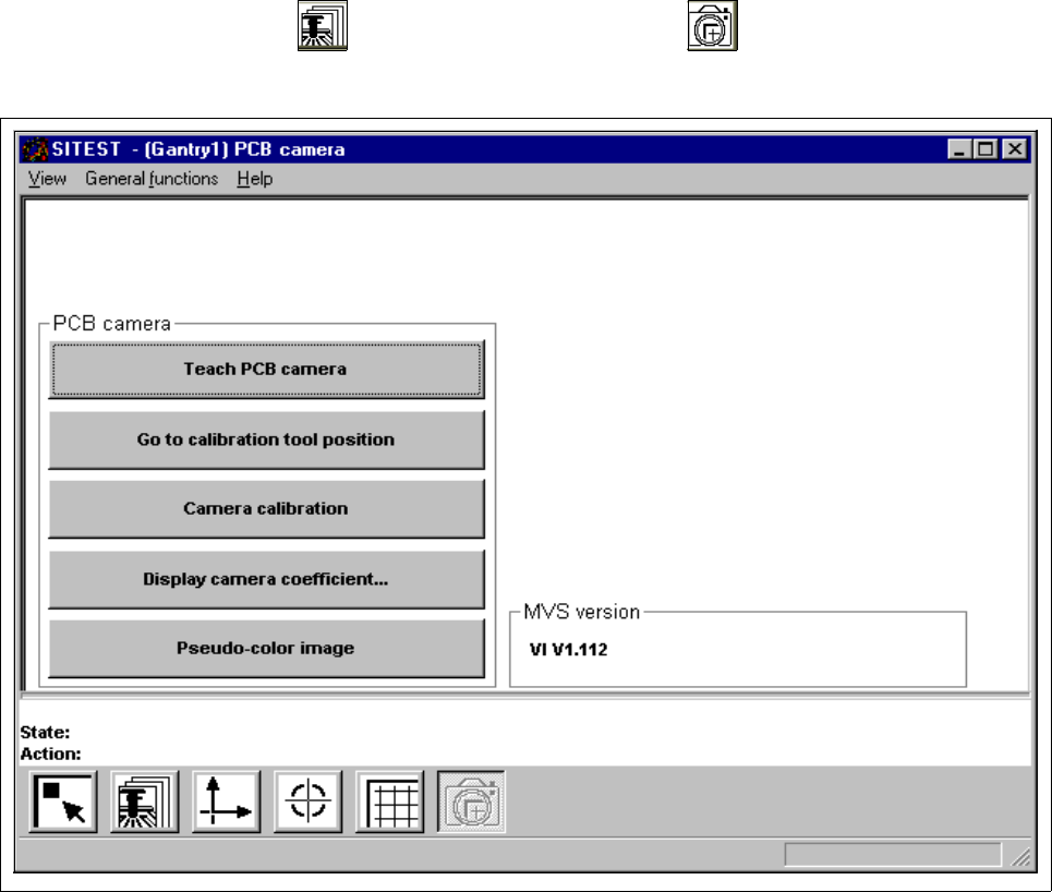
Fig. 3.3.1 "PCB camera functions" Display
Overview of the functions:
– Teach PCB camera to call up the teaching functions
– Go to calibration tool position to approach the fiducial position (calibration tool)
– Camera calibration to calibrate the PCB camera
– Display camera coefficient to display the PCB camera values determined
– Pseudo-color image to switch the screen display to the pseudo-color image mode
to view the results of any illumination changes

3 Calibration Functions User Manual Test Program SITEST
3.3 PCB Camera Calibration Software Version 405.xx Issue 01/99
3 - 8
● Click on the
Camera calibration
button.
The calibration procedure is performed on the PCB camera of the active gantry.
NOTE
The values thus determined can be displayed after the completion of the calibration procedure using the
Display camera coefficient...
function.
3
● Click on the icon to return to the main view.
User Manual Test Program SITEST 3 Calibration Functions
Software Version 405.xx Issue 01/99 3.4 RV Camera Calibration
3 - 9
3.4 RV Camera Calibration
● Carry out the preparatory steps proceeding as described in section 3.1.
● In the main view click on the icon or or to switch the screen display to the "RV head"
display (see Fig. 0.3.4) of the desired RV head.
● Click on the icon to switch to the "RV head / RV camera" display.
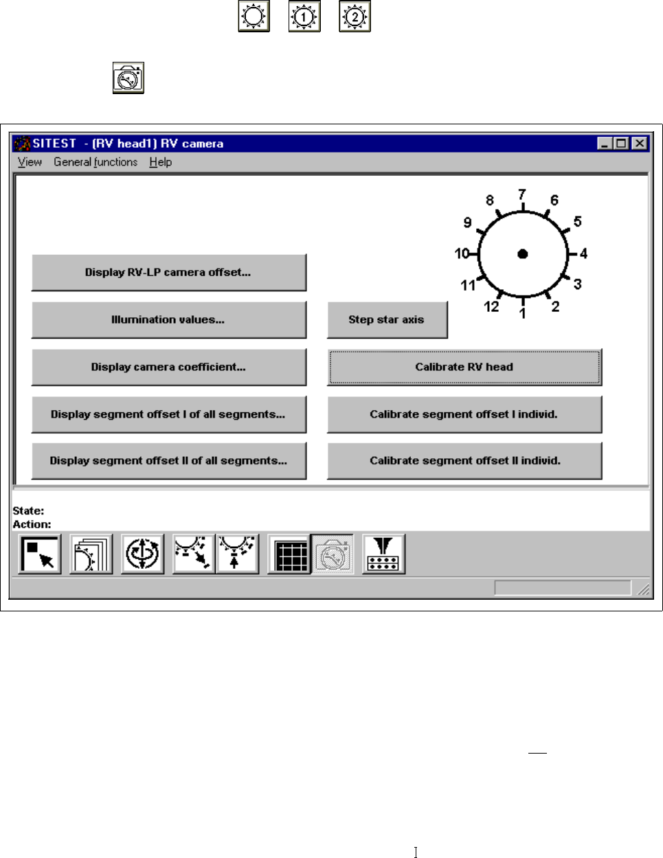
Fig. 3.4.1 "RV head / RV camera" Display
Overview of the functions:
– Display RV-PCB camera offset... to display the offset values of RV-PCB camera
– Illumination values... to display the illumination values
(Normally, the illumination values do not
need to be
changed. Changing the values in a non-expert manner will
lead to incorrect calibration results).
– Display camera coefficient... to display the RV camera values determined
– Display segment offset I of all segments... to display the x and y-offset values determined under
"Segment offset
"