00191332-01.pdf - 第129页
User Manual Test Program SITEST 3 Calibration Functions Software Version 405.xx Issue 01/99 3.8 Calibration of the IC Nozzle Changer (SIPLACE 80F4/80F5) 3 - 17 3.8 Calibrati on of the IC Noz zle Changer (SIPLA CE 80 F 4 …
3 Calibration Functions User Manual Test Program SITEST
3.7 Calibration of the IC Camera (SIPLACE 80F4/80F5) Software Version 405.xx Issue 01/99
3 - 16
● Click on the
Calibrate IC head / camera
button.
The complete calibration will now be performed.
● If you wish to view the values determined after the completion of the calibration procedure, click on the
Display camera coefficient...
button.
● If you wish to view the values for the camera position and focus height, click on the
Display camera
and focus position...
button.
A comparison of the current versus the previous camera data (camera position in x and y-directions and
focus height) is displayed.
NOTE
The x and y-values of the current camera position are also displayed in the "Camera position" field.
● Click on the icon to return to the main view.
User Manual Test Program SITEST 3 Calibration Functions
Software Version 405.xx Issue 01/99 3.8 Calibration of the IC Nozzle Changer (SIPLACE 80F4/80F5)
3 - 17
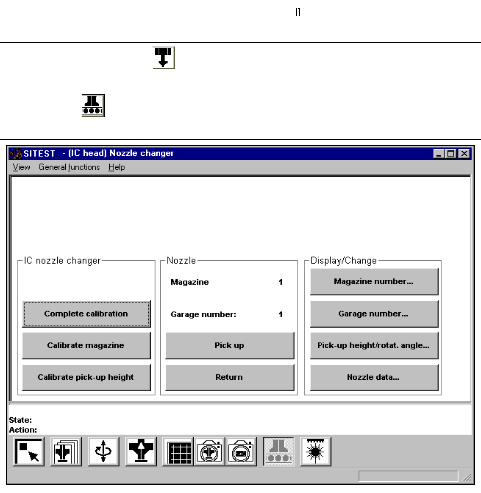
3.8 Calibration of the IC Nozzle Changer
(SIPLACE 80F
4
/80F
5
)
Verify that the calibration data for the PCB camera, segment offset (RV-PCB camera offset), IC head,
IC camera and machine zero point have already been determined.
3
● In the main view click on the icon to switch the screen display to the "IC head" display
(see Fig. 0.3.6).
● Click on the icon to switch to the "IC nozzle changer" display.
Fig. 3.8.1 "IC nozzle changer" Display
Overview of the functions:
– Complete calibration to determine the x and y-positions for each magazine
– Calibrate magazine to determine the x and y-positions for the current magazine
– Calibrate pick-up height to determine the pick-up height for the current magazine

3 Calibration Functions User Manual Test Program SITEST
3.8 Calibration of the IC Nozzle Changer (SIPLACE 80F4/80F5) Software Version 405.xx Issue 01/99
3 - 18
– Pick up to pick up the nozzle from the selected garage of the current magazine
– Return to deposit the nozzle in the selected garage of the current magazine
– Magazine number... to open the input box for the magazine number
– Garage number... to open the input box for the garage number
– Pick-up height/rotat.angle... to display the values for the x and y-positions, the pick-up height and
the rotational angle of the current garage in the current magazine
(the data may be edited if required).
– Nozzle data... to display for the current magazine the x, y and z-values determined
NOTE
The "Complete calibration" function is used if the nozzle changer is completely equipped with all
4 magazines.
If the nozzle changer is not
completely occupied, it is necessary to determine separately for each maga-
zine the x-, y- and z-values using the functions "Calibrate magazine" and "Calibrate pick-up height".
3
● Click on the
Complete calibration
button.
The PCB camera approaches the measuring holes of all magazines in the nozzle changer.
The x and y-values for each garage are calculated from the positions determined.
● Click on the
Nozzle data...
button. A comparison of the setpoint values versus the actually determined
values in x and y-directions is displayed on the screen for each garage of the current magazine. The z-
position (pick-up height) is displayed in addition.
● If the nozzle changer is not completely equipped with magazines, click on the
Magazine number...
but-
ton. The input box for the magazine number opens.
● Enter the desired magazine number and confirm your entry by clicking on
Accept
.
● Click on the
Calibrate magazine
button.
The PCB camera approaches the measuring hole of the selected magazine. The x and y-values for
each magazine compartment are calculated from the position determined.
Calibration of the pick-up height
NOTE
The pick-up height must be determined for each magazine.
3
● To determine the pick-up height, enter the numbers of the desired garage and the desired magazine
prior to the calibration procedure using the Garage number... and Magazine number... functions.
NOTE
For the calibration of the pick-up height, a nozzle must be attached to the segment located at the
bottom and the selected garage must be empty. 3