00191332-01.pdf - 第143页
User Manual Test Program SITEST 3 Calibration Functions Software Version 405.xx Issue 01/99 3.12 Measuring the Position of PCB Reference Corner I (and that of PCB Reference Corner II) 3 - 31 ● In th e main vie w clic k o…
3 Calibration Functions User Manual Test Program SITEST
3.12 Measuring the Position of PCB Reference Corner I (and that of PCB Reference Corner II) Software Version 405.xx Issue 01/99
3 - 30
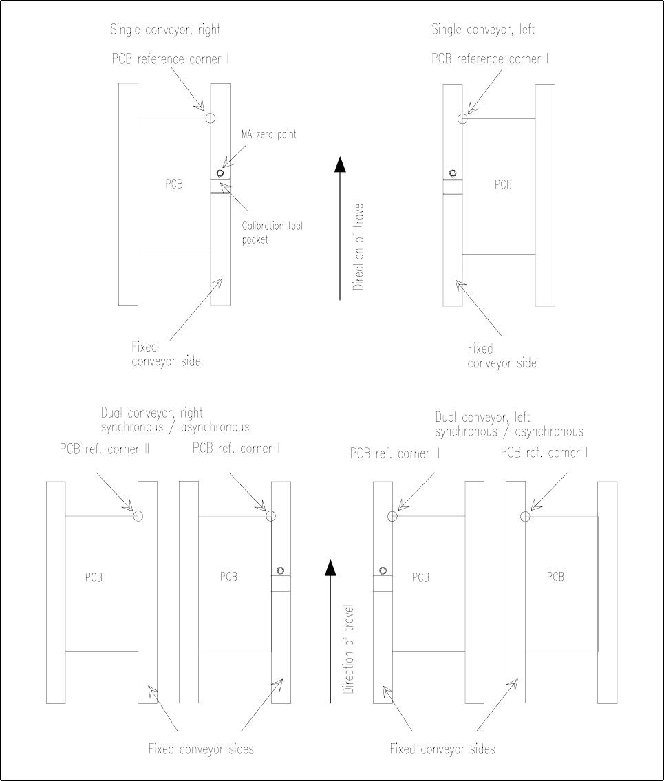
Fig. 3.12.1 Location of the PCB Reference Corners
User Manual Test Program SITEST 3 Calibration Functions
Software Version 405.xx Issue 01/99 3.12 Measuring the Position of PCB Reference Corner I (and that of PCB Reference Corner II)
3 - 31
● In the main view click on the icon (for gantry 1 of SIPLACE 80S-20/S-23) or the icon (for the
gantry of SIPLACE 80F
4
/80F
5
)
to switch the screen display to the "Gantry" display (see Fig. 0.3.4).
● Click on the icon to reach the "Calibrate positions" display (see Fig. 3.5.1).
● To check the PCB reference corner position, click on the
Approach
button in the "Position of PCB refer-
ence corner" field. The gantry moves the PCB camera over the PCB reference corner position I.
The screen display is switched to the PCB camera.
● Check whether the "PCB reference corner I" is visible in the PCB camera’s field of view.
● Press
ESC
to return the screen display to the normal program mode.
● To correct the position of the PCB reference corner, click on the
Teach
button in the "Position of PCB
reference corner" field.
The setting box for teaching the gantry opens, and the screen display is switched to the PCB camera
(for details on the procedure for moving the gantry during the teaching operation, refer to chapt. 1, sec-
tion 1.6).
● Teach the PCB reference corner I using the cursor keys ↑↓ ← →.
● When teaching has been completed, press
ESC
to return the screen display to the normal program
mode.
● Click on the
Cancel
button in the setting box. The taught position is accepted. The position values for x
and y are displayed in the "Position of PCB reference corner" field.
● If a dual conveyor is installed on the machine, click on the
Approach
button in the "PCB reference cor-
ner position 2" field.
The gantry moves the PCB camera over the PCB reference corner position II.
The screen display is switched to the PCB camera.
● All further steps are to be performed in the same way as described for the PCB reference corner I.
● Click on the icon to return to the main view.
● Load the PCB(s) into the output conveyor using the conveyor functions (see chapt. 2, section 2.5).
● Click on the icon to return to the main view.
3 Calibration Functions User Manual Test Program SITEST
3.12 Measuring the Position of PCB Reference Corner I (and that of PCB Reference Corner II) Software Version 405.xx Issue 01/99
3 - 32