00191332-01.pdf - 第86页
2 Functions for the Adjustment of the Machine User Manual Test Program SITEST 2.1 Axis Functions Software Version 405.xx Issue 01/99 2 - 14 2.1.4 WPC Axis Functions (SIPLA CE 80 F 4 /80F 5 ) ● In the "Wafflepack Cha…
User Manual Test Program SITEST 2 Functions for the Adjustment of the Machine
Software Version 405.xx Issue 01/99 2.1 Axis Functions
2 - 13
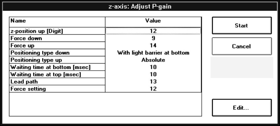
Adjusting the P gain for the z-axis:
● Click on the
Adjust P-gain...
button. The following setting box opens.
● All further steps are the same as described in section 2.1.1, page 2 - 9.
Adjusting the P gain for the d-axis:
● To adjust the P gain of the d-axis, click on the
Adjust P-gain...
button.
The setting box for the parameter group opens.
● All further steps are the same as described in section 2.1.1, page 2 - 6.
● If the calibration tool position is to be approached, click on the
Calibration tool pos.
button (see Fig.
2.1.3).
2 Functions for the Adjustment of the Machine User Manual Test Program SITEST
2.1 Axis Functions Software Version 405.xx Issue 01/99
2 - 14
2.1.4 WPC Axis Functions (SIPLACE 80F
4
/80F
5
)
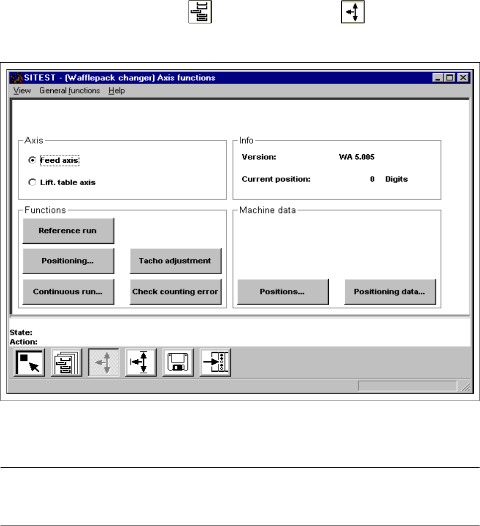
● In the "Wafflepack Changer" display (see Fig. 0.3.10) click on the icon to switch to the
"WPC axis functions" display.
Fig. 2.1.4 "WPC axis functions" Display
To perform the individual functions, proceed as follows:
NOTE
Since the layout of some of the setting boxes is identical or similar to that for the gantry axis functions (see
section 2.1.1), these boxes will not be described and displayed again in this section.
2
● In the "Axis" field activate the radio button for the axis to be adjusted ("Feed axis" or "Lift. table axis").
● Select the Axis reference run function if the axis has not been referenced yet.
● To move the axis to a given position in one operation, click on the Position axis button. The setting box
for the "Target position" and "Positioning type" opens. All further steps are the same as described in
section 2.1.1.
User Manual Test Program SITEST 2 Functions for the Adjustment of the Machine
Software Version 405.xx Issue 01/99 2.1 Axis Functions
2 - 15
● If the selected axis is to be positioned in the continuous run mode, click on the
Continuous run
button. The setting box for the positioning data opens. All further steps are the same as described in
section 2.1.1.
● If the tacho is to be adjusted to the final speed, click on the
Tacho adjustment...
button. The continu-
ous run for the adjustment of the tacho is started.
All further steps are the same as described in section 2.1.1.
● Click on the
Counting error
button if you wish to start a check of the counting errors for the currently
active axis. On starting the check, a dialog box opens in which a value is displayed after the check
representing the counting error of the axis (in digits or "counts").
● To acknowledge this display, click on the
OK
button in the dialog box.
● If you wish to change the values for the machine parameters "Zero point cor.value", "Maximum position"
and "Minimum position", click on the
Positions...
button.
A setting box opens. All further steps are the same as described in section 2.1.1.
● If you wish to view the machine parameter values, click on the
Positioning data...
button.