00191332-01.pdf - 第128页
3 Calibration Functions User Manual Test Program SITEST 3.7 Calibration of the IC Camera (S IPLACE 80F4/80F5) Software Version 405.xx Issue 01/99 3 - 16 ● Clic k on the Calibrate I C head / camera button. The comp lete c…
User Manual Test Program SITEST 3 Calibration Functions
Software Version 405.xx Issue 01/99 3.7 Calibration of the IC Camera (SIPLACE 80F4/80F5)
3 - 15
3.7 Calibration of the IC Camera (SIPLACE 80F
4
/80F
5
)
● Carry out the preparatory steps proceeding as described in section 3.1.
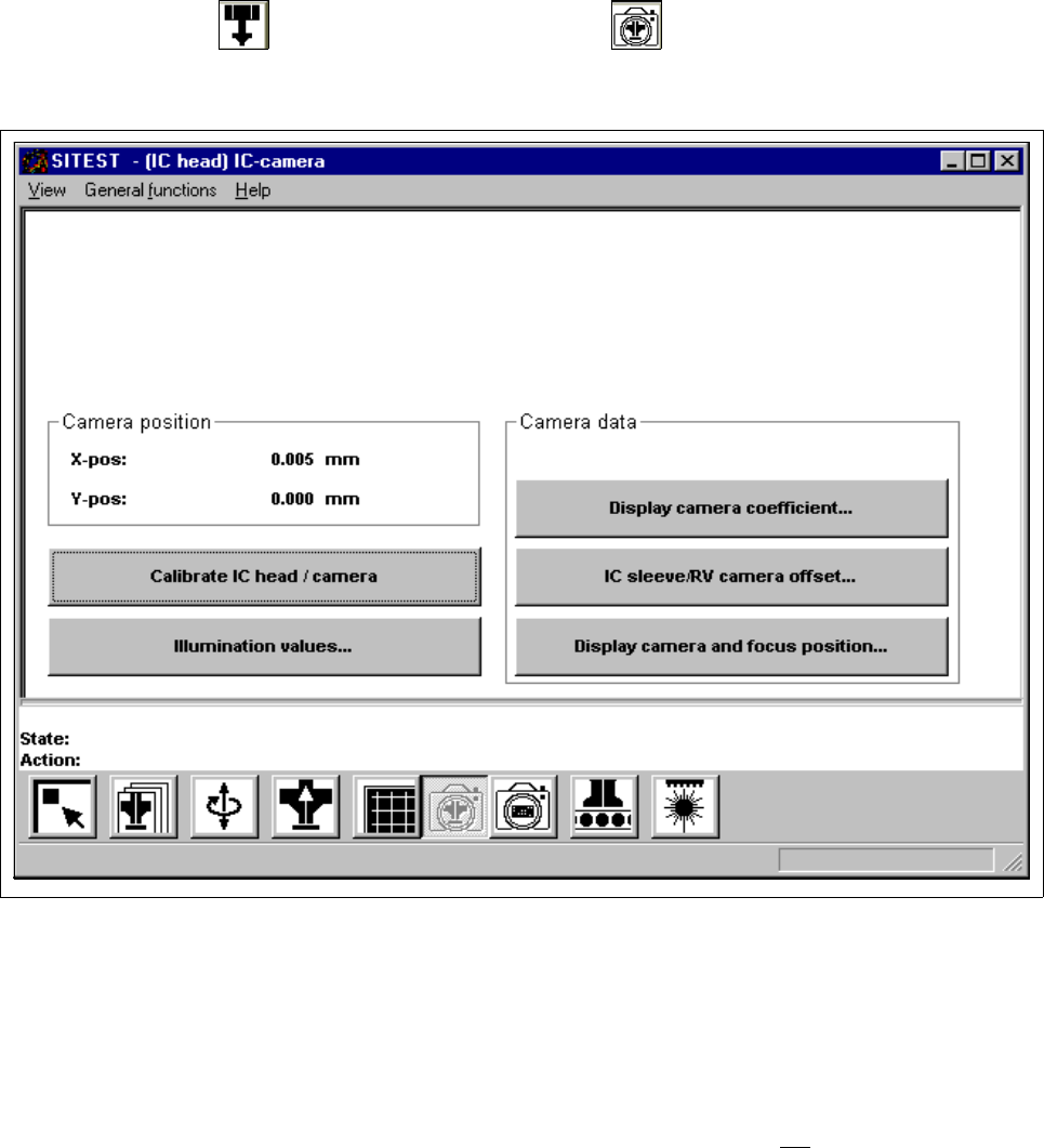
● In the "IC head" display (see Fig. 0.3.6) click on the icon to switch to the "IC head /
IC camera" display.
Fig. 3.7.1 "IC head / IC camera" Display
Overview of the functions:
– Calibrate IC head / camera to calibrate the IC head and the IC camera
– Illumination values... to display the illumination values
(Normally, the illumination values do not
need to be changed.
Changing the values in a non-expert manner will lead to
incorrect calibration results).
– Display camera coefficient... to display the IC camera values determined
– IC sleeve/RV camera offset... to display the offset between IC sleeve and RV camera in x and
y-direction, determined during calibration
– Display camera and focus position... to display the camera position and focus height determined

3 Calibration Functions User Manual Test Program SITEST
3.7 Calibration of the IC Camera (SIPLACE 80F4/80F5) Software Version 405.xx Issue 01/99
3 - 16
● Click on the
Calibrate IC head / camera
button.
The complete calibration will now be performed.
● If you wish to view the values determined after the completion of the calibration procedure, click on the
Display camera coefficient...
button.
● If you wish to view the values for the camera position and focus height, click on the
Display camera
and focus position...
button.
A comparison of the current versus the previous camera data (camera position in x and y-directions and
focus height) is displayed.
NOTE
The x and y-values of the current camera position are also displayed in the "Camera position" field.
● Click on the icon to return to the main view.
User Manual Test Program SITEST 3 Calibration Functions
Software Version 405.xx Issue 01/99 3.8 Calibration of the IC Nozzle Changer (SIPLACE 80F4/80F5)
3 - 17
3.8 Calibration of the IC Nozzle Changer
(SIPLACE 80F
4
/80F
5
)
Verify that the calibration data for the PCB camera, segment offset (RV-PCB camera offset), IC head,
IC camera and machine zero point have already been determined.
3
● In the main view click on the icon to switch the screen display to the "IC head" display
(see Fig. 0.3.6).
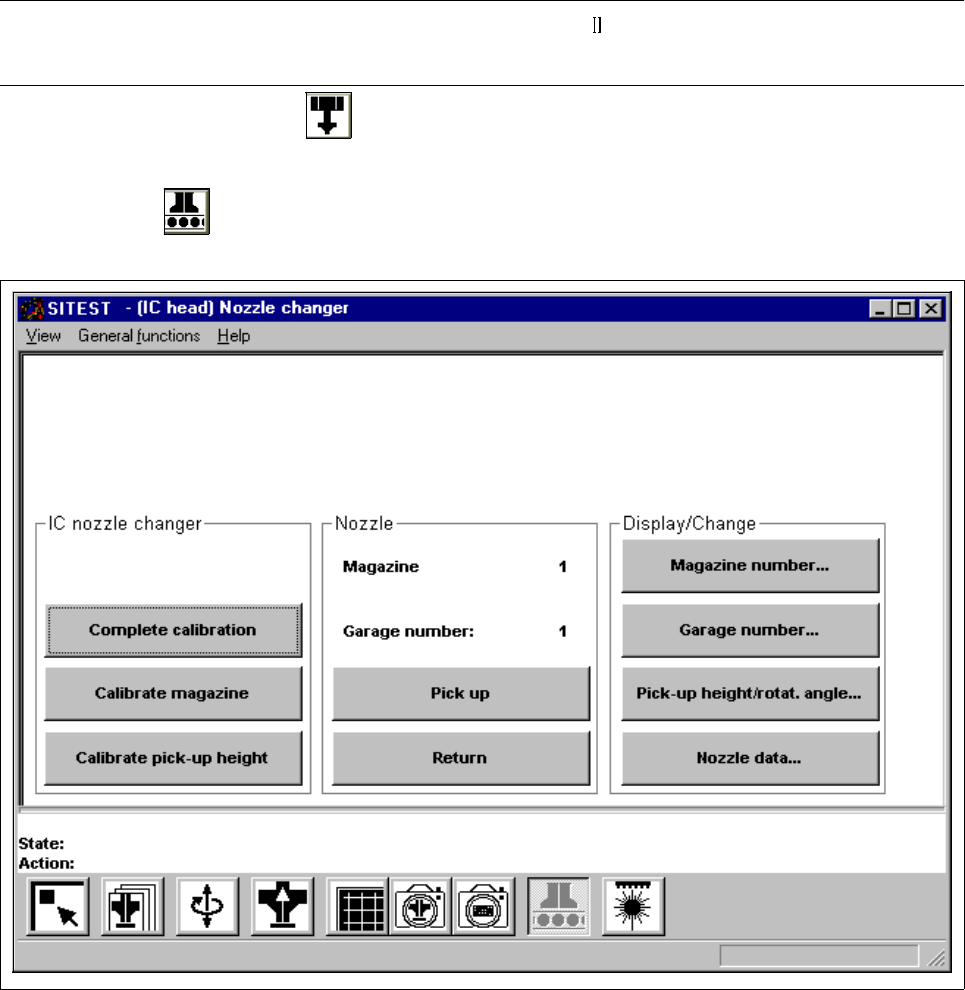
● Click on the icon to switch to the "IC nozzle changer" display.
Fig. 3.8.1 "IC nozzle changer" Display
Overview of the functions:
– Complete calibration to determine the x and y-positions for each magazine
– Calibrate magazine to determine the x and y-positions for the current magazine
– Calibrate pick-up height to determine the pick-up height for the current magazine