00191332-01.pdf - 第152页
4 Mapping User Manual Test Program SITEST 4.1 Preparatory Steps for the Mapping Operation Software Version 405.xx Issue 01/99 4 - 4

User Manual Test Program SITEST 4 Mapping
Software Version 405.xx Issue 01/99 4.1 Preparatory Steps for the Mapping Operation
4 - 3
4.1 Preparatory Steps for the Mapping Operation
● In the main view click on the
Overall reference run
button to perform a reference run of all gantry and
head axes.
NOTE
For RV and IC mapping a mapping plate with a dark, dull surface must be used.
In the case of dual conveyors, mapping must be performed for the right and left conveyor tracks.
4
CAUTION
!
On no account
must the PCB clamping mechanism be actuated during PCB mapping
. If the glass map-
ping plate for PCB mapping is clamped, it may be damaged so severely, that it cannot be used any more.
4

4 Mapping User Manual Test Program SITEST
4.1 Preparatory Steps for the Mapping Operation Software Version 405.xx Issue 01/99
4 - 4
User Manual Test Program SITEST 4 Mapping
Software Version 405.xx Issue 01/99 4.2 PCB Mapping
4 - 5
4.2 PCB Mapping
NOTE
Verify that the calibration data for the RV camera, PCB camera, segment offset
(RV-PCB camera offset) and
the MA zero point have already been determined. Furthermore, prior to the performance of the mapping, the
width adjustment must have been calibrated.
4
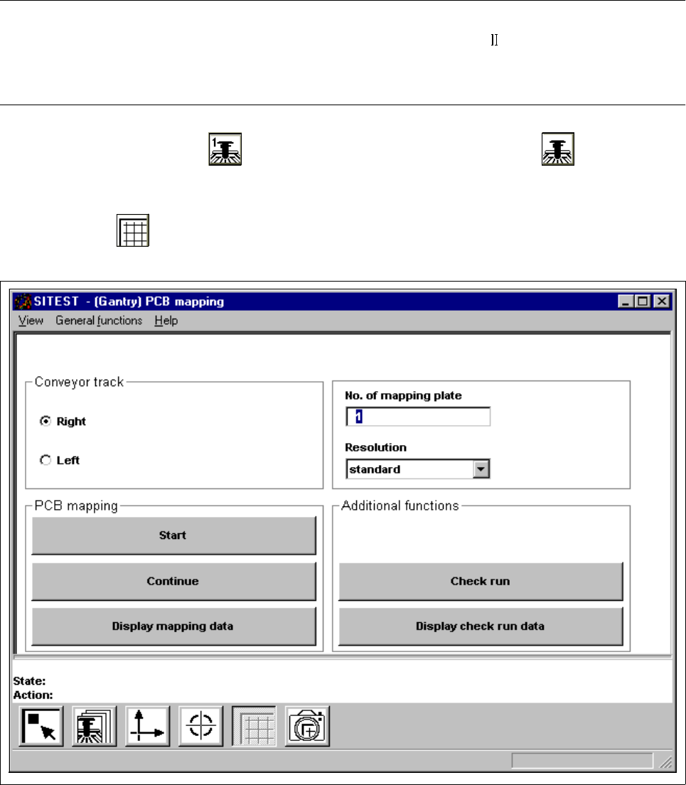
● In the main view click on the icon (for gantry 1 of SIPLACE 80S-20/S-23) or the icon (for the
gantry of SIPLACE 80F
4
/80F
5
)
to switch the screen display to the "Gantry" display (see Fig. 0.3.4).
● Click on the icon to switch to the "PCB mapping" display.
Fig. 4.2.1 "PCB mapping" Display