00191332-01.pdf - 第146页
3 Calibration Functions User Manual Test Program SITEST 3.13 Measuring the Pick-Up Positions of Tracks 1 and 120 Software Version 405.xx Issue 01/99 3 - 34 Fig. 3.13.1 "Pick-up position track 1 and t rack 120" …
User Manual Test Program SITEST 3 Calibration Functions
Software Version 405.xx Issue 01/99 3.13 Measuring the Pick-Up Positions of Tracks 1 and 120
3 - 33
3.13 Measuring the Pick-Up Positions of Tracks
1 and 120
NOTE
Verify that the calibration data for segment offset II (RV-PCB camera offset), PCB camera and machine zero
point have already been determined.
3
● Place the setting gauge onto track 1 or 120 of the component table to be measured.
NOTE
Prior to the measuring operation, check the component table surface underneath the setting gauge for
any unevenness or contamination.
● In the main view click on the icon or to switch the screen display to the "Table" display (see
Fig. 0.3.9) of the desired component table.
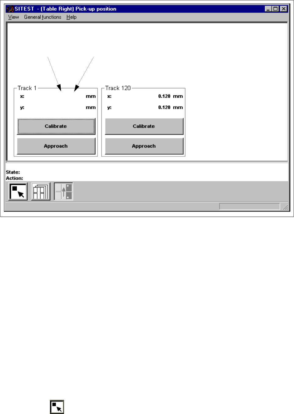
● Click on the icon to switch to the "Pick-up position track 1 and track 120" display.
3 Calibration Functions User Manual Test Program SITEST
3.13 Measuring the Pick-Up Positions of Tracks 1 and 120 Software Version 405.xx Issue 01/99
3 - 34
Fig. 3.13.1 "Pick-up position track 1 and track 120" Display
● Depending on the position of the setting gauge on the component table, click on the
Approach
button
in the "Track 1" field or in the "Track 120" field.
The current gantry moves with the PCB camera to a point above the calibration hole in the setting
gauge.
The screen display is switched to the PCB camera.
● Check whether the calibration hole can be seen in the search area of the PCB camera.
● Press
ESC
to return the screen display to the normal program mode.
● Depending on the position of the setting gauge on the component table, click on the
Calibrate
button in
the "Track 1" field or in the "Track 120" field. The calibration of the selected track is performed.
The position values for x and y are displayed in the "Track 1" or the "Track 120" field.
● Proceed in the same way for the other track.
● Perform the steps described above also for the other component table.
● Click on the icon to return to the main view.
Current value Old value
0.001 (0.001)
0.001 (0.001)

User Manual Test Program SITEST
Software Version 405.xx Issue 01/99
4 - I
Table of Contents
Page
Mapping
4.1 Preparatory Steps for the Mapping Operation. . . . . . . . . . . . . . . . . . . . . . . . . . . . . . . . . . 4 - 3
4.2 PCB Mapping . . . . . . . . . . . . . . . . . . . . . . . . . . . . . . . . . . . . . . . . . . . . . . . . . . . . . . . . . . . . 4 - 5
4.2.1 Mapping Run for Both Gantries (SIPLACE 80S-20/S-23) . . . . . . . . . . . . . . . . . . . . . . . . . . .4 - 7
4.2.2 Mapping Run for the Active Gantry . . . . . . . . . . . . . . . . . . . . . . . . . . . . . . . . . . . . . . . . . . . . 4 - 7
4.3 RV Mapping. . . . . . . . . . . . . . . . . . . . . . . . . . . . . . . . . . . . . . . . . . . . . . . . . . . . . . . . . . . . . . 4 - 9
4.3.1 Mapping Run for Both Gantries (SIPLACE 80S-20/S-23) . . . . . . . . . . . . . . . . . . . . . . . . . .4 - 11
4.3.1.1 Mapping Run for the Active Gantry . . . . . . . . . . . . . . . . . . . . . . . . . . . . . . . . . . . . . . . . . . . 4 - 11
4.4 IC Mapping . . . . . . . . . . . . . . . . . . . . . . . . . . . . . . . . . . . . . . . . . . . . . . . . . . . . . . . . . . . . . 4 - 13