00191332-01.pdf - 第123页
User Manual Test Program SITEST 3 Calibration Functions Software Version 405.xx Issue 01/99 3.5 Calibration of the Machine Zero Point 3 - 11 3.5 Calibration of the Machi ne Zer o P oint NOTE V eri fy that th e calibra ti…

3 Calibration Functions User Manual Test Program SITEST
3.4 RV Camera Calibration Software Version 405.xx Issue 01/99
3 - 10
– Display segment offset
of all segments... to display the x and y-offset values determined under
"Segment offset II"
– Step star axis to index the star
– Calibrate RV head to calibrate the RV camera, segment offsets I and II
nd
the RV-PCB camera offset
– Calibrate segment offset I individ. to determine segment offset I for the currently selected
segment (= segment in the lower position)
– Calibrate segment offset II individ. to determine segment offset II for the currently selected
segment (= segment in the lower position)
● Click on the
Calibrate RV head
button.
The calibration will be performed in the following sequence:
– calibration of the RV camera
– determination of segment offset I for all 12 or 6 segments
– determination of segment offset II for all 12 or 6 segments
Segment offsets II are determined with the z-axis extended. The measurement is performed
repeatedly for each segment. The average value is calculated for each segment from the
measured values determined. The RV-PCB camera offset refers to segment I.
● If you wish to determine segment offset I or II for a particular segment, first click on the
Step star axis
button repeatedly until the number of the desired segment (center sleeve) is displayed in the bottom
position.
● Click on the
Calibrate segment offset I individ.
or
Calibrate segment offset II individ.
button.
The respective segment offset will be determined for the selected segment.
NOTE
The functions “Calibrate segment offset I individ.” and “Calibrate segment offset II individ.”
are only intended for error analysis purposes if the calibration of the RV head could not be carried out
successfully.
After the determination of individual segment offsets, the RV head must be completely recalibrated.
NOTE
After the completion of the calibration procedure it is possible to display the values determined during
the calibration of the RV camera by means of the Display camera coefficient... function.
The values determined for the segment offsets can be displayed using the Display segment offset I of
all segments... or Display segment offset II of all segments..., respectively.
● Click on the icon to return to the main view.
User Manual Test Program SITEST 3 Calibration Functions
Software Version 405.xx Issue 01/99 3.5 Calibration of the Machine Zero Point
3 - 11
3.5 Calibration of the Machine Zero Point
NOTE
Verify that the calibration data for the RV camera, segment offset II (RV-PCB camera offset) and PCB camera
have already been determined.
On SIPLACE 80S-20/S-23 machine types, the calibration of the machine zero point must be performed for both
gantries directly one after the other!
The MA zero point (measuring hole) is integrated on the fixed conveyor side in the same segment as the cali-
bration tool pocket (see Fig. 3.12.1 in section 3.12). This applies to all conveyor types!
3
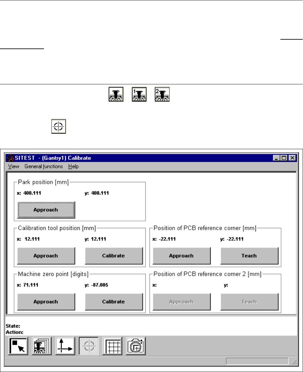
● In the main view click on the icon or or to switch the screen display to the "Gantry"
display (see Fig. 0.3.4) of the desired gantry.
● Click on the icon to switch to the "Calibrate positions" display.
Fig. 3.5.1 "Calibrate positions" Display

3 Calibration Functions User Manual Test Program SITEST
3.5 Calibration of the Machine Zero Point Software Version 405.xx Issue 01/99
3 - 12
● Click on the
Approach
button in the "Machine zero point" field.
The active gantry moves the PCB camera over the measuring hole for the MA zero point.
The screen display is switched to the PCB camera.
● Check whether the measuring hole for the machine zero point is visible in the camera’s field of view.
NOTE
If the measuring hole is not visible in the camera’s field of view, the value for the zero point correction
has to be changed (see chapt. 2, section 2.1.1, page 2 - 5).
● Press
ESC
to return the screen display to the normal program mode.
● Click on the
Calibrate
button in the "Machine zero point" field.
The calibration of the machine zero point will now be performed. The position values for x and y are dis-
played in the "Machine zero point" field.
● Click on the icon to return to the main view.