00197279-03_SM_Glue-Feeder_EN.pdf - 第45页
Replacing Spare Parts 3.14.2 Inserting the Actuator O-Ring and Guide Bushing Guide Bushing Service Manual SIPLACE Glue Feeder 45 ► From above, fit the actuator O-ring onto the jet p lung - er. ► From above, fit the O-rin…
Replacing Spare Parts
Guide Bushing 3.14.2 Inserting the Actuator O-Ring and Guide Bushing
44 Service Manual SIPLACE Glue Feeder
3.14.2
3.14.2 Inserting the Actuator O-Ring and Guide Bushing
Inserting the Actuator O-Ring and Guide Bushing
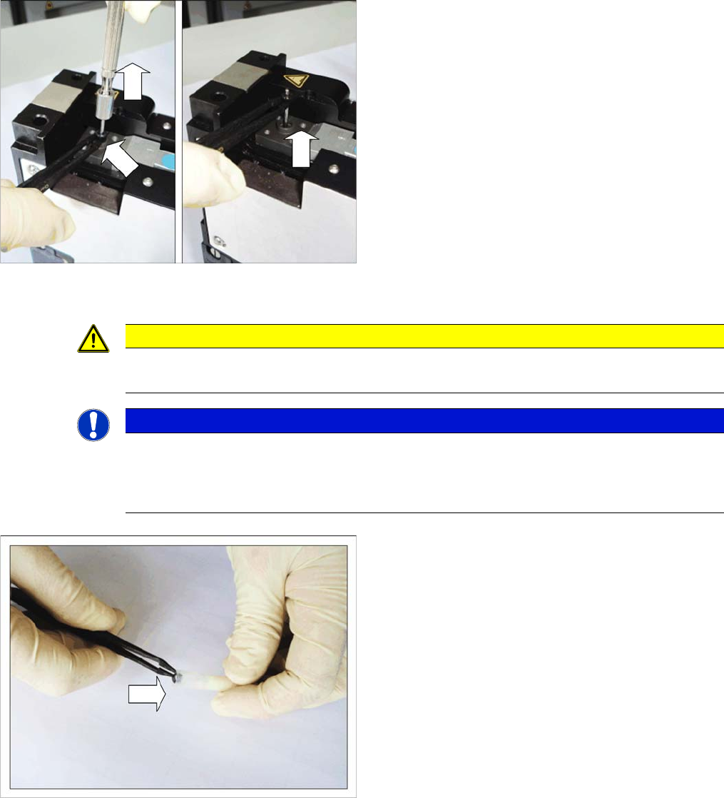
► From above, fit the plunger service tool vertically onto
the jet plunger again.
► Turn the plunger service tool clockwise until tight
-
ened.
► Pull the plunger service tool vertically upwards, to
-
gether with the jet plunger.
► Use the antistatic tweezers to hold the actuator O-
ring tight.
► Turn the plunger service tool anticlockwise until loos
-
ened.
► Use the antistatic tweezers to lift the actuator O-ring
vertically upwards and off the jet plunger.
CAUTION
Poisonous and hazardous substances
To avoid direct contact with the glue, always wear protective gloves during this work.
NOTICE
Replace the O-ring
Damaged O-rings are no longer able to fulfil their sealing function. As a result, the pressure re
-
quired at the jet valve can not be produced to its full extent. We therefore recommend that you
also replace the actuator O-ring when you replace the guide bushing.
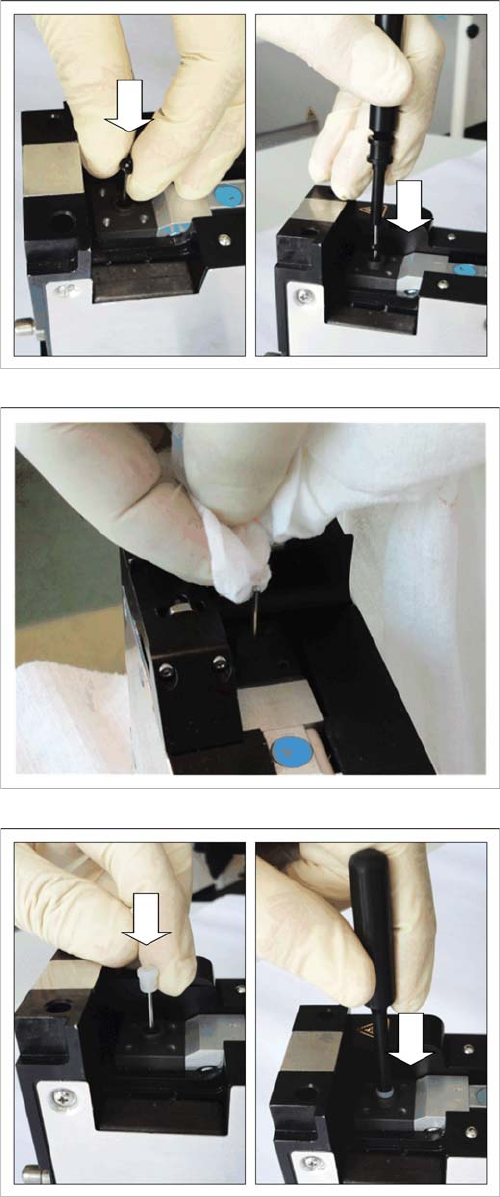
► Coat the actuator O-ring with a little O-ring NBR in
-
side grease (special grease for actuator O-rings).
Replacing Spare Parts
3.14.2 Inserting the Actuator O-Ring and Guide Bushing Guide Bushing
Service Manual SIPLACE Glue Feeder 45
► From above, fit the actuator O-ring onto the jet plung
-
er.
► From above, fit the O-ring service tool vertically onto
the jet plunger and push the actuator O-ring as far as
possible (end stop) onto the jet plunger.
► Remove the O-ring service tool.
► Clean the jet plunger with a cleansing tissue.
► From above, fit the guide bushing onto the jet plung
-
er.
► From above, fit the O-ring service tool vertically onto
the jet plunger and push the guide bushing as far as
possible (end stop) onto the jet plunger.
► Remove the O-ring service tool.
► Fit the jet block (see "3.13.2 Fitting the Jet Block"
[➙40]).
► Fit the cartridge pipe, nozzle heating and cartridge
into place (see "3.11.2 Fitting the Cartridge Pipe"
[➙32])
Replacing Spare Parts
Jet Valve P-DOT 3.15.1 Removing the Jet Valve P-DOT
46 Service Manual SIPLACE Glue Feeder
3.15
3.15 Jet Valve P-DOT
Jet Valve P-DOT
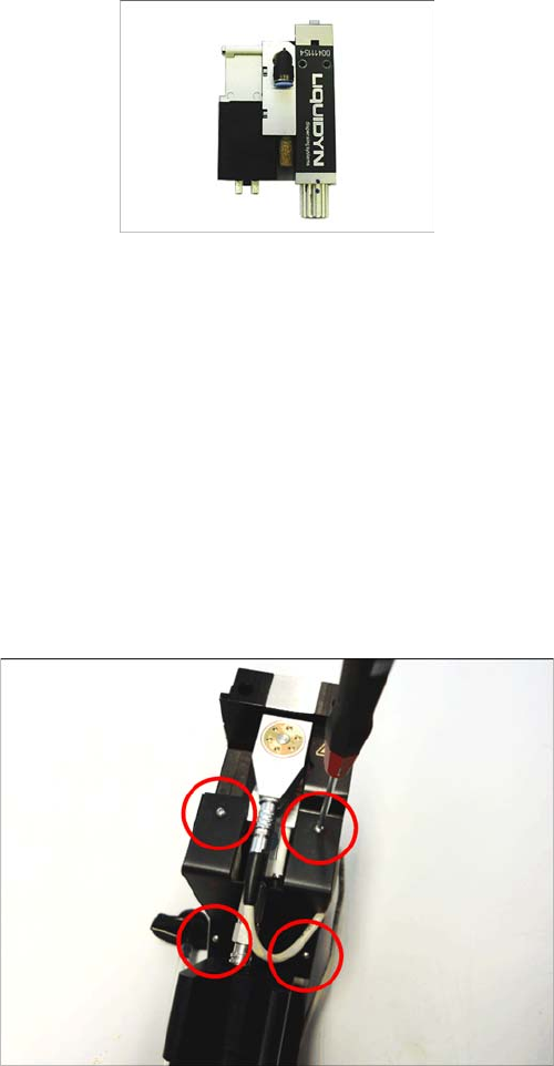
Required spare parts
Jet valve P-DOT with modified cable, item no. 03096487-xx
Required tools
▪ Allen key size 1.5
▪ Allen key size 2
▪ Allen key size 2.5
▪ Heating key (on the Glue Feeder)
▪ Open-ended wrench, size 8
▪Tweezers
▪ Measuring system for plunger setting
3.15.1
3.15.1 Removing the Jet Valve P-DOT
Removing the Jet Valve P-DOT
► Remove the right side cover (see "3.8.1 Removing
the Right Side Cover" [ ➙ 21])
► Remove the cartridge.
► Remove the 4 marked screws which fasten the cover
plate to the frame. Use a size 1.5 Allen key for this.