00197279-03_SM_Glue-Feeder_EN.pdf - 第61页
Replacing Spare Parts 3.15.3 Jet Valve P-DOT - Setting the Jet Plunger Jet Valve P-DOT Service Manual SIPLACE Glue Feeder 61 ► Use a pair of t weezers to move the locking pla te un - der the setting button (as shown) and…
Replacing Spare Parts
Jet Valve P-DOT 3.15.3 Jet Valve P-DOT - Setting the Jet Plunger
60 Service Manual SIPLACE Glue Feeder
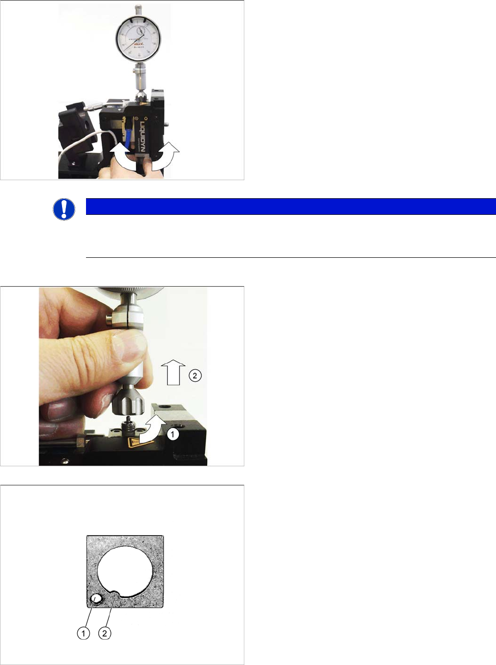
By turning the setting button, you can adjust the height of
the jet plunger. The measuring system shows the value
set.
► Set the default value to a height of 0.6 mm.
The value of 0.6 mm corresponds to 60N. If you alter the
value by 0.1 mm, the spring pre-tension will be changed
by 10N.
A jet plunger height of 0.8 mm corresponds to 80N.
NOTICE
Settings
Observe the instruction about the effect of higher or lower jet plunger settings in the Glue Feed
-
er user manual (00197218-xx).
► Once you have set the height of the jet plunger, loos
-
en the connection nut with an anticlockwise rotation
from the jet block. (1)
► Lift the measuring system vertically up and off the jet
block. (2)
► Fit the nozzle heating (see section "3.9.2 Fitting the
Nozzle Heating" [ ➙ 23]).
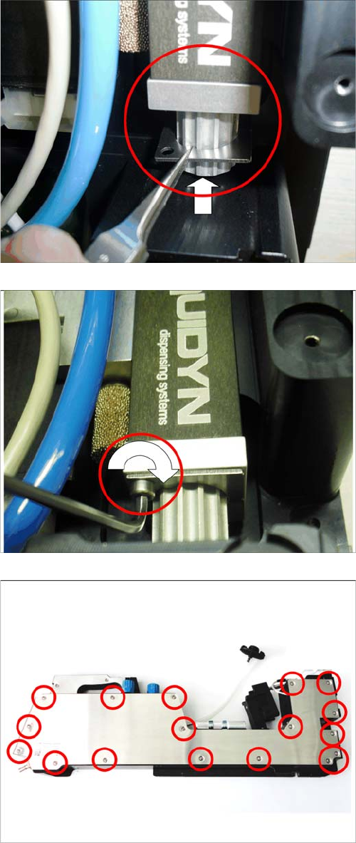
► Secure the setting screw against incorrect adjust
-
ment with the locking plate.
When pushing the locking plate into place, make sure
that the hole in the plate (1) is over the thread hole in the
jet valve. This is essential for fastening the locking plate.
The nibs of the locking plate (2) need to be guided into
one of the grooves on the setting screw. If necessary, you
may need to move the setting screw so that the nib has
room.
Replacing Spare Parts
3.15.3 Jet Valve P-DOT - Setting the Jet Plunger Jet Valve P-DOT
Service Manual SIPLACE Glue Feeder 61
► Use a pair of tweezers to move the locking plate un
-
der the setting button (as shown) and then upwards.
► Use the shortened size 2 hexagon socket spanner to
fix the locking plate to the jet valve P-DOT.
► Fit the right side cover (see section "3.8.2 Fitting the
Right Side Cover" [ ➙ 21]).
Replacing Spare Parts
Pressure Control Valves 3.16.1 Pressure Control Valve (Dispenser)
62 Service Manual SIPLACE Glue Feeder
3.16
3.16 Pressure Control Valves
Pressure Control Valves
3.16.1
3.16.1 Pressure Control Valve (Dispenser)
Pressure Control Valve (Dispenser)
Required spare parts
Pressure control valve LR-M7-D-O-7 assembly, item no. 03097857-xx
Required tools
▪ Open-ended wrench, size 24
3.16.1.1
3.16.1.1 Removing the Pressure Control Valve (Dispenser)
Removing the Pressure Control Valve (Dispenser)
► Remove the right side cover (see "3.8.1 Removing
the Right Side Cover" [ ➙ 21])
► Pull the cover on the pressure control valve up and
off. (1)
► Remove the nut fastening the pressure control valve.
Use a size 24 fork wrench for this. (2)
► Carefully pull the pressure control valve vertically
downwards and out of the glue feeder frame.
► Mark the back hose with adhesive tape.
► Remove the hoses from the pressure control valve.