00197279-03_SM_Glue-Feeder_EN.pdf - 第93页
Replacing Spare Parts 3.24.2 Fitting the Handle Assembly Handle assembly Service Manual SIPLACE Glue Feeder 93 ► As sh own in the diagram, plug the pressure control valve into the glue feeder fra me. ► Faste n the pres s…
Replacing Spare Parts
Handle assembly 3.24.2 Fitting the Handle Assembly
92 Service Manual SIPLACE Glue Feeder
3.24.2
3.24.2 Fitting the Handle Assembly
Fitting the Handle Assembly
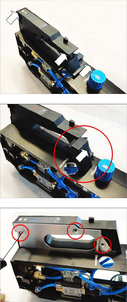
► As shown in the diagram, push the handle at the side
onto the glue feeder frame.
► As shown in the diagram, push the handle cover at
the side into the glue feeder handle.
► As shown in the diagram, fasten the cover plate with
the 3 marked Torx screws. Use a size T8 TORX
screwdriver for this.
Replacing Spare Parts
3.24.2 Fitting the Handle Assembly Handle assembly
Service Manual SIPLACE Glue Feeder 93
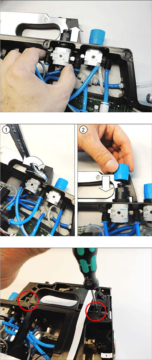
► As shown in the diagram, plug the pressure control
valve into the glue feeder frame.
► Fasten the pressure control valve with a nut. Use a
size 24 fork wrench for this. (1)
► Fit the cover as far as possible onto the pressure con
-
trol valve. (2)
► Fasten the right side cover (see "3.8.2 Fitting the
Right Side Cover" [ ➙ 21])
► Fasten the handle using the two marked Torx screws.
Use a size T8 TORX screwdriver for this.
Replacing Spare Parts
Handle assembly 3.24.2 Fitting the Handle Assembly
94 Service Manual SIPLACE Glue Feeder
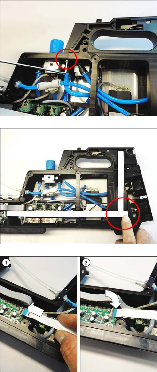
► Fasten the marked Allen screw. Use a size 2.5 Allen
key for this.
► Run the flat ribbon cable as shown in the diagram.
► Carefully fold the flat ribbon cable as marked in the di
-
agram.
Make sure that the blue surface at the end of the ca
-
ble is at the top.
► Use double-sided adhesive band to fix the flat ribbon
cable at the marked place to the glue feeder frame.
► Insert the flat ribbon cable as far as possible into the
connection.
Make sure that the blue surface at the end of the ca
-
ble is at the top and that the flat ribbon cable lies
straight in the connection.
► Swing the lock on the connection down.
Make sure that the flat ribbon cable is fitted firmly in
the connection. Tug gently on the cable to check.
► Check again whether the flat ribbon cable is fitted
straight in the connection.
If necessary, open the connection and correct the po
-
sition of the flat ribbon cable before closing the con
-
nection again.
► Fasten the left side cover (see "3.7.2 Fitting the Left
Side Cover" [ ➙ 20].