00197279-03_SM_Glue-Feeder_EN.pdf - 第58页
Replacing Spare Parts Jet Valve P-DOT 3.15.3 Jet Valve P-DOT - Setting the Jet Plunge r 58 Service Manual SIPLACE Glue Feeder 3.15.3.2 3 . 1 5 . 3 . 2 S e t t in g t h e J e t P lu n g e r Setting the Jet Plunger ► Rem o…
Replacing Spare Parts
3.15.3 Jet Valve P-DOT - Setting the Jet Plunger Jet Valve P-DOT
Service Manual SIPLACE Glue Feeder 57
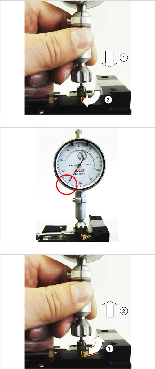
► Fit the measuring system and connection nut vertical
-
ly on the jet block from above. (1)
► Turn the connection nut clockwise as far as the end
stop on the jet block. (2)
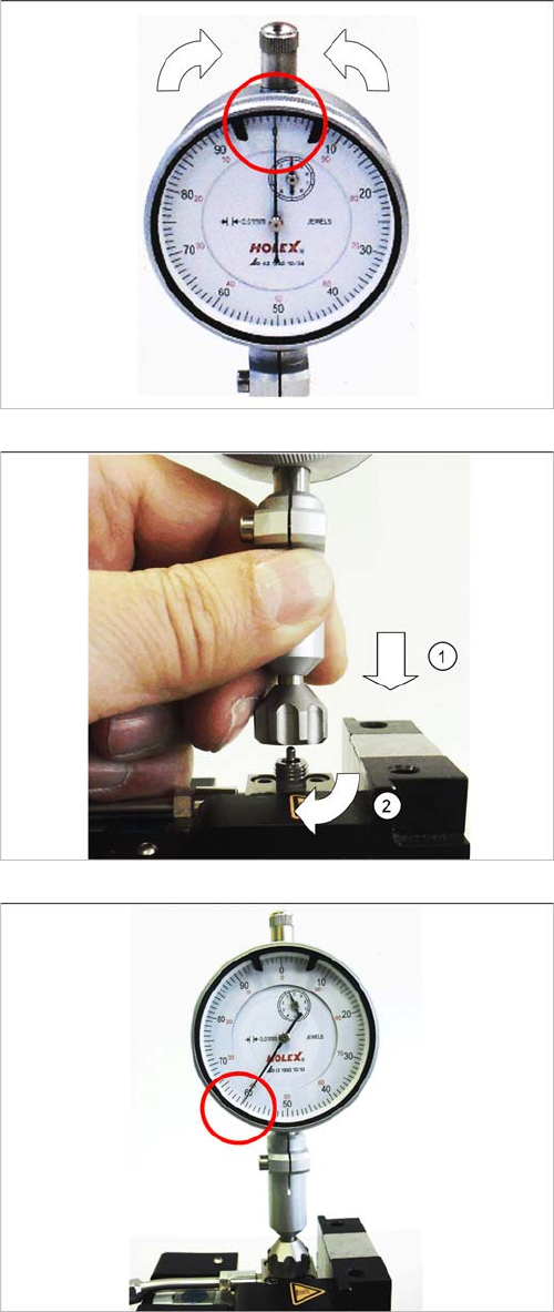
The large pointer shows the current height of the jet
plunger. The example in the diagram shows 0.6 mm.
0.6 mm height corresponds to the default factory setting
and is optimum for normal use of the Glue Feeder.
If a deviating value is shown, you will need to correct the
height.
For a description of how to change the height, refer to
section "3.15.3 Jet Valve P-DOT - Setting the Jet Plung
-
er" [ ➙ 56].
The jet plunger setting check has now been completed.
► Turn the connection nut anticlockwise to loosen it
from the jet block. (1)
► Lift the measuring system vertically up and off the jet
block. (2)
► Fit the nozzle heating (see section "3.9.2 Fitting the
Nozzle Heating" [ ➙ 23]).
Replacing Spare Parts
Jet Valve P-DOT 3.15.3 Jet Valve P-DOT - Setting the Jet Plunger
58 Service Manual SIPLACE Glue Feeder
3.15.3.2
3.15.3.2 Setting the Jet Plunger
Setting the Jet Plunger
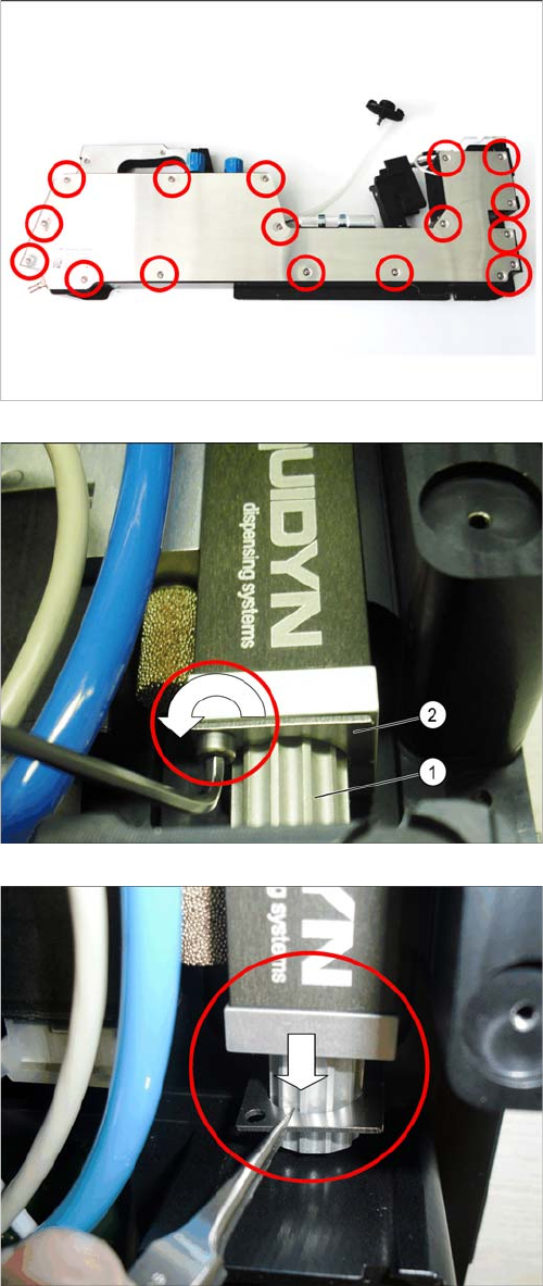
► Remove the right side cover (see section "3.8.1 Re
-
moving the Right Side Cover" [ ➙ 21]).
The setting screw (1) on the jet valve is secured with a
locking plate (2) to prevent incorrect adjustment.
► Use the shortened size 2 hexagon socket spanner to
loosen the screw which is fixed to the jet valve with
the locking plate.
► Use a pair of tweezers to pull the locking plate down
and out, under the setting screw.
Replacing Spare Parts
3.15.3 Jet Valve P-DOT - Setting the Jet Plunger Jet Valve P-DOT
Service Manual SIPLACE Glue Feeder 59
► Remove the nozzle heating (see section "3.9.1 Re
-
moving the Nozzle Heating" [ ➙ 22]).
► Before you fit the measuring system, turn the setting
ring of the measuring system until the large pointer
points to the 0.
► Fit the measuring system and connection nut vertical
-
ly on the jet block from above. (1)
► Turn the connection nut clockwise as far as the end
stop on the jet block. (2)
The large pointer shows the current setting of the plung
-
er.