SPF维修.pdf - 第25页
SPF SERVICE MANUAL 2.0−2 D54SEC−1 1−000−A0 D54SEC−1 1−000−A0 Sentence No. 2.INST ALLA TION This chapter describes information on Panasert installation. · Be sure to read ’Safety Precautions’ in this manual carefully .

SERVICE MANUAL
SPF
2.0−1
2ダミー(Sectionのレベル1)
2.0ダミー(Sectionのレベル2)

SPF
SERVICE MANUAL
2.0−2
D54SEC−11−000−A0
D54SEC−11−000−A0
Sentence No.
2.INSTALLATION
This chapter describes information on Panasert installation.
· Be sure to read ’Safety Precautions’ in this manual carefully.
2.1 Installation Procedure
SERVICE MANUAL
SPF
2.1−1
D54SEC−11−040−C0
2.1 Installation Procedure
D54SEC−11−040−C0
Sentence No.
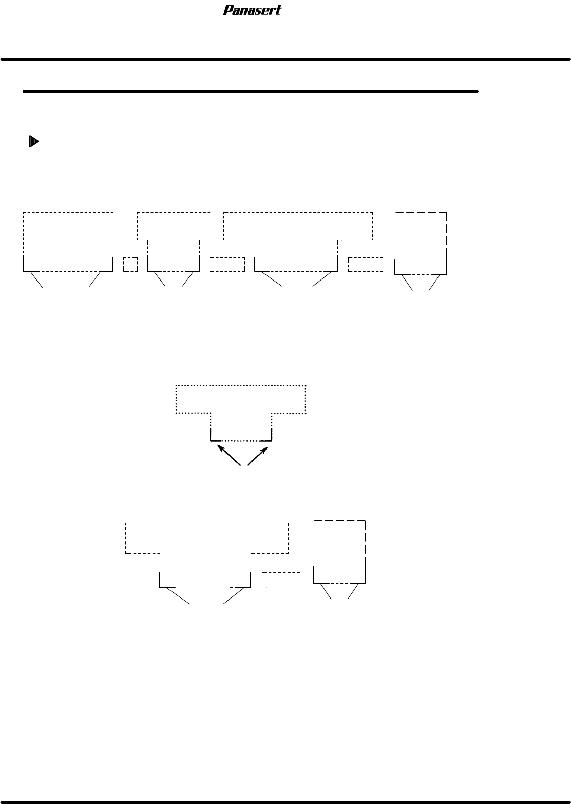
2.1.1 Installation Position
Installation position
1. Decide machine installation position from layout diagram. (CAD diagram, etc.)
2. Mark the reference points of each machine on the floor with a maker pen, etc.
=HINT=
In most cases the machine front corners are used as reference points.
REF−G1
MSF
MSR
Reference point
*C−CON
Reference point
Reference point
C−CON
C−CON
Reference point
SPF
*C−CON are connection conveyors which stand between machines.
3. Install the main body of each machine temporarily at reference point. (Except for C-CON, etc.)
4. In the case of chip mounting line, the installation should start from the heaviest machine.
(MSR, etc.).
Reference point
MSR
5. Install SPF based on the heaviest machine (MSR) as reference.
MSR
C−CON
Reference point
Reference point
SPF