SPF维修.pdf - 第58页
(−) limit sensor (+) limit sensor Origin sensor Origin Mechanical stopper (−) limit 0 28 −4 −2 Stroke related diagram (+) limit 27 ± 0.5 +0.5 0 +0.5 −1. 0 Mechanical stopper 4.2 Lower Section Unit : Others SERVICE MANUAL…
2mm
45mm
Reference 0
Main stage section
A
Height measuring jig
Dial gauge
Height
measuring
jig
Rail guide
LM guide
attachment
surface
ST axis motor
View from A
Sub stage table
SPF
4.2 Lower Section Unit : Others
SERVICE MANUAL
4.2−4
D54SEC−W4−600−B0
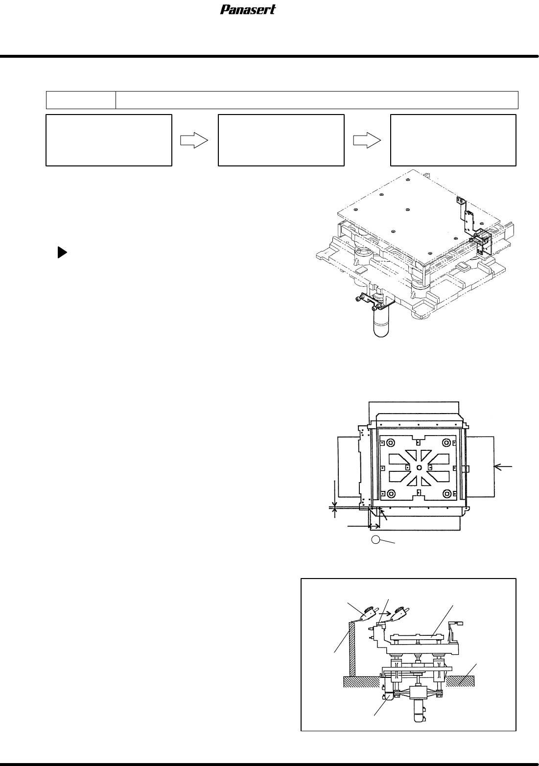
4.2.3 ST Axis (Stage Up/Down Axis) Origin Adjustment
Unit No. 1080804100
ST Axis (Stage Up/Down Axis)
Origin Adjustment
Maintenance Manual /
MAINTENANCE GUIDE /
Screen Holder Coplanarity and
Height Adjustment
4.2.2 ST Axis (Stage Up/Down
Axis) Motor Replacement
=Preparation=
1. Dial gauge
2. Magnet stand
3. Height measuring jig
4. Vinyl tape
ST axis origin adjustment
1. Remove the power supplier protection cover.
=REMARKS=
To prevent from the short circuit inside the
power supplier, be sure to cover with the
insulating protection sheet to the power
supplier.
2. Turn the power [ON] and return to origin.
3. Move the SY axis to 200mm.
4. Attach the magnet stand to the camera axis.
5. Touch the dial gauge at the left reference surface
on the fixed rail guide (the position where 2mm
from within the rail guide and 45mm from the left
side).
6. Zero the dial gauge.
7. Check the height from the X axis LM guide
attachment surface to the rail guide upper
surface.
=Specification=
Height : 349.05 to 349.10mm
=HINT=
Be sure to use the height measuring jig. Be
sure to adjust the height 349.0mm to the
screen holder upper surface as the setting
reference.
(−) limit sensor
(+) limit sensor
Origin sensor
Origin
Mechanical stopper
(−) limit
0
28
−4
−2
Stroke related diagram
(+) limit
27±0.5
+0.5
0
+0.5
−1.0
Mechanical stopper
4.2 Lower Section Unit : Others
SERVICE MANUAL
SPF
4.2−5
D54SEC−W4−600−B0
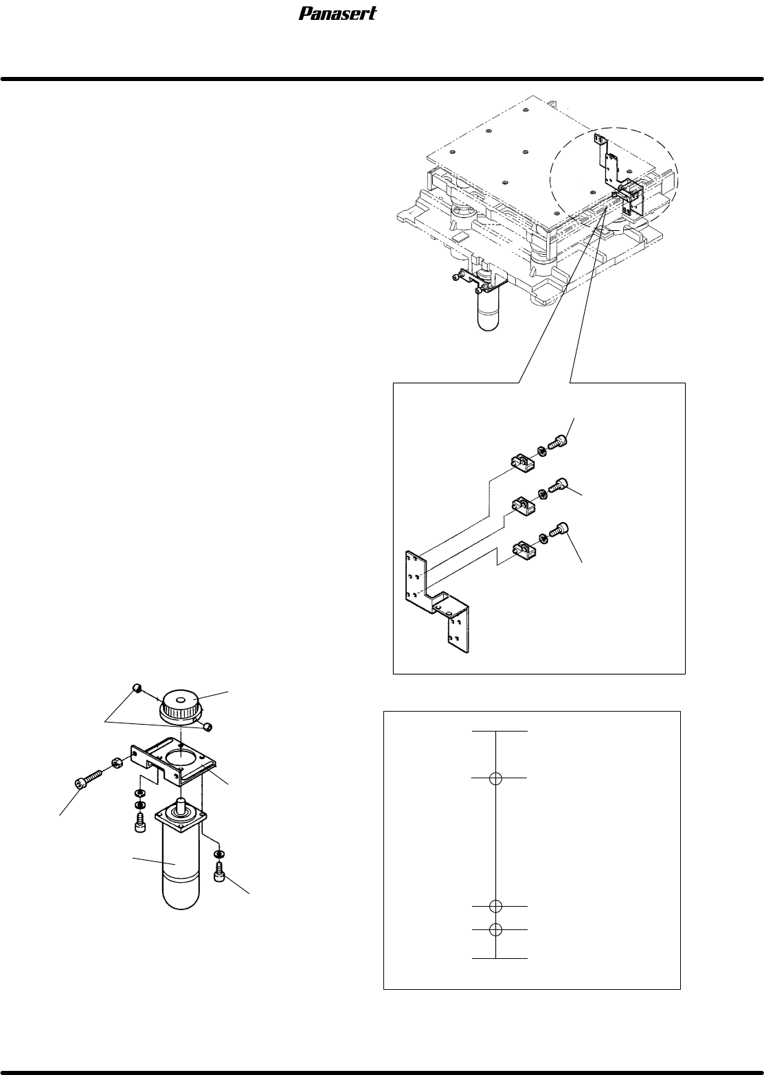
8. If not within the specification, turn “SERVO
MOTOR” on the main control panel [OFF].
9. Move the stage to any position where you can
adjust it easily.
10. Attach the dial gauge to the rail guide.
11. Zero the dial gauge.
12. Loosen the cotters.
13. Rotate the pulley and adjust the height.
14. Tighten the cotters.
15. Check the height of the height measuring jig and
the rail guide again.
16. Adjust the dog so that the origin sensor detects
correctly.
17. Turn “SERVO MOTOR” on the main control
panel [ON].
18. Return to origin of the ST axis and check the
origin sensor detects correctly again.
=CHECK=
Be sure to check the symmetry of the origin
sensor.
19. Check the height of the stage, the loader rail and
the unloader rail.
=CHECK=
Make sure that there is no interference for the
PCB transfer.
20. Check the height of the screen holder as the basis
for the stage height.
21. Check the (±) limit sensors.
=Specification=
(+) limit : 27±0.5
(−) limit : −2
+0.5
−1.0
Cotters
ST axis motor
Pulley
Bracket
Bolt (A)
Bolt (B)
Stage
Fixed rail guide
Reference mark
OK
NG
Position error
Stage Y axis motor
Coupling
Coupling bolt
Motor bolt
Reference mark
Stage Y axis motor
SPF
4.2 Lower Section Unit : Others
SERVICE MANUAL
4.2−6
D54SEC−W4−600−B0
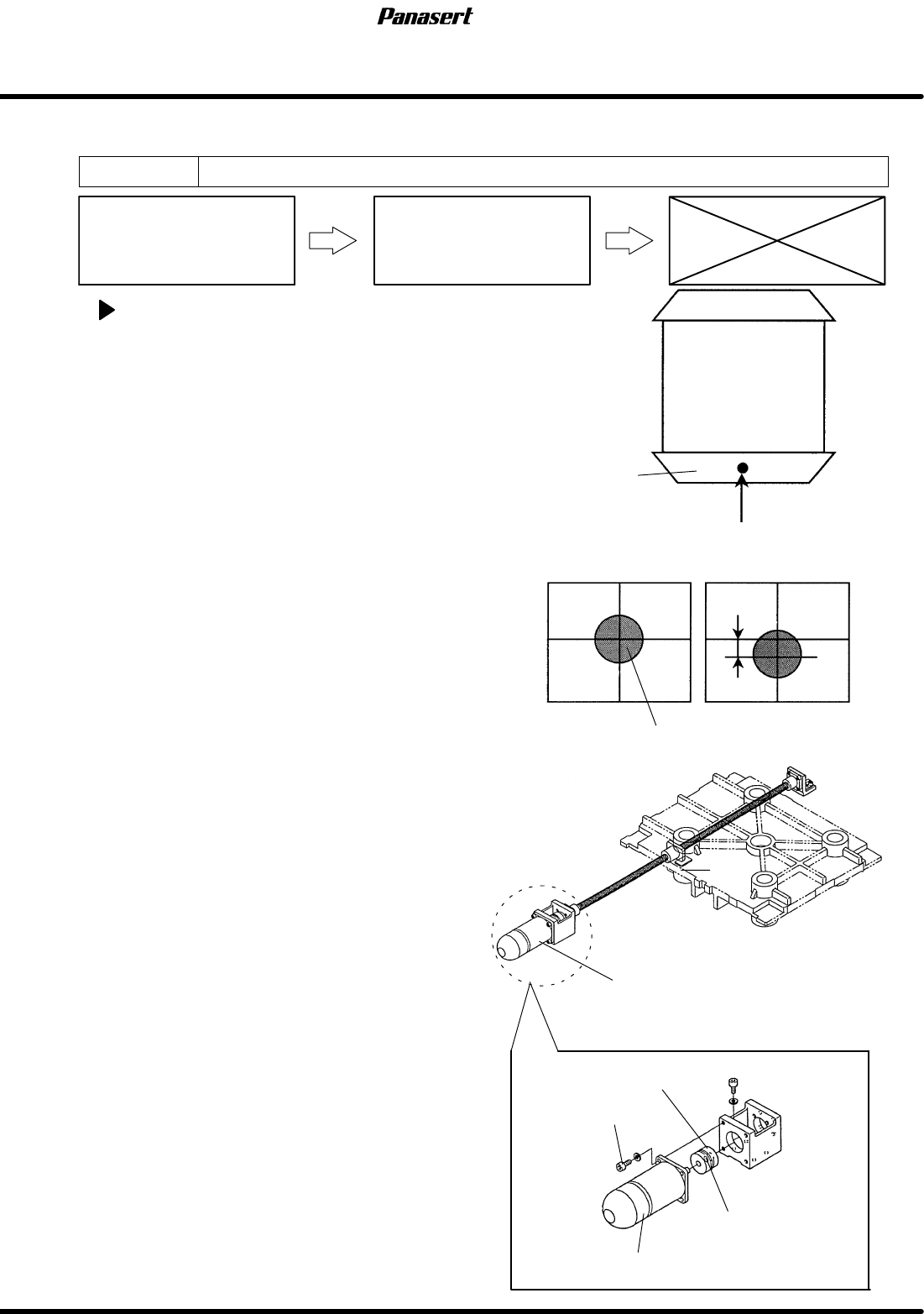
4.2.4 SY Axis (Stage Y Axis) Origin Adjustment
Unit No. 1080804200
SY Axis (Stage Y Axis) Origin
Adjustment
4.2.1 SY Axis (Stage Y Axis)
Motor Replacement
SY axis origin adjustment
1. Turn the power [ON] and return to origin.
2. Move the SY axis (stage Y axis) to 150mm.
3. Move the ST axis to 26mm.
4. Move the CY axis to 624.5mm.
5. Turn “RECOG LIGHT RING” on the sub control
panel [ON].
6. Check visually that the reference mark matches
with the center of the cross line on the monitor
screen.
7. If not, loosen the coupling bolt on the ball screw
side.
8. Rotate the ball screw while watching the monitor
screen until the reference mark matches with the
center of the cross line on the monitor screen.
9. Tighten the coupling bolt on the ball screw side.
10. Check that the sensor dog matches with the origin
sensor.
11. If not, move the sensor dog and the sensor until it
matches.