SPF维修.pdf - 第89页
SPF 5.1 AC Servo Gain Adjustment SERVICE MANUAL 5.1−2 D54SEC−84−040−A0 AC servo driver dip switch setting Switch setting Switch setting is as the following tables. No. Specification Setting SW1 Position loop gain ON : Ga…
5.1 AC Servo Gain Adjustment
SERVICE MANUAL
SPF
5.1−1
D54SEC−84−040−A0
5.1 AC Servo Gain Adjustment
D54SEC−84−040−A0
Sentence No.
=Preparation=
1. Oscilloscope
=HINT=
When the machine is in the following status, AC servo gain adjustment is required.
1. ’Driver error’ or ’Motor movement impossible’ is displayed.
2. Motor is noisy.
3. Motor or driver is replaced.
4. Motor movement is abnormal.
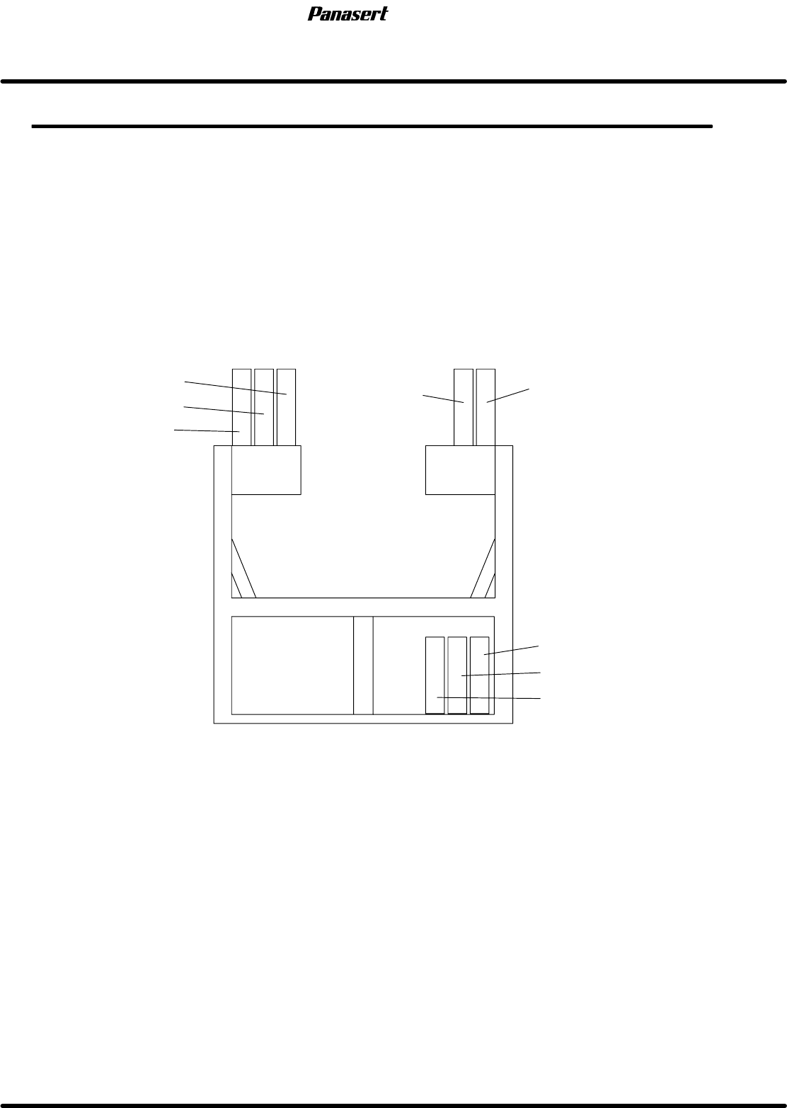
SY axis
ST axis
SST axis
CX axis
CY axis
SCX axis
SCR axis
SQ axis
Main body rear
AC servo motor drivers location
SPF
5.1 AC Servo Gain Adjustment
SERVICE MANUAL
5.1−2
D54SEC−84−040−A0
AC servo driver dip switch setting
Switch setting
Switch setting is as the following tables.
No.
Specification Setting
SW1
Position loop gain
ON : Gain setting range high gain
OFF : Gain setting range low gain
OFF
SW2
Speed loop gain
ON : Gain setting range high gain
OFF : Gain setting range low gain
OFF
SW3
Speed monitor output
ON : 127kpps / 2.5V
OFF : 5000rpm / 2.5V
OFF
SW4
Speed monitor output
ON : 2500 pulses / 2.5V
OFF : 100rpm / 2.5V
OFF
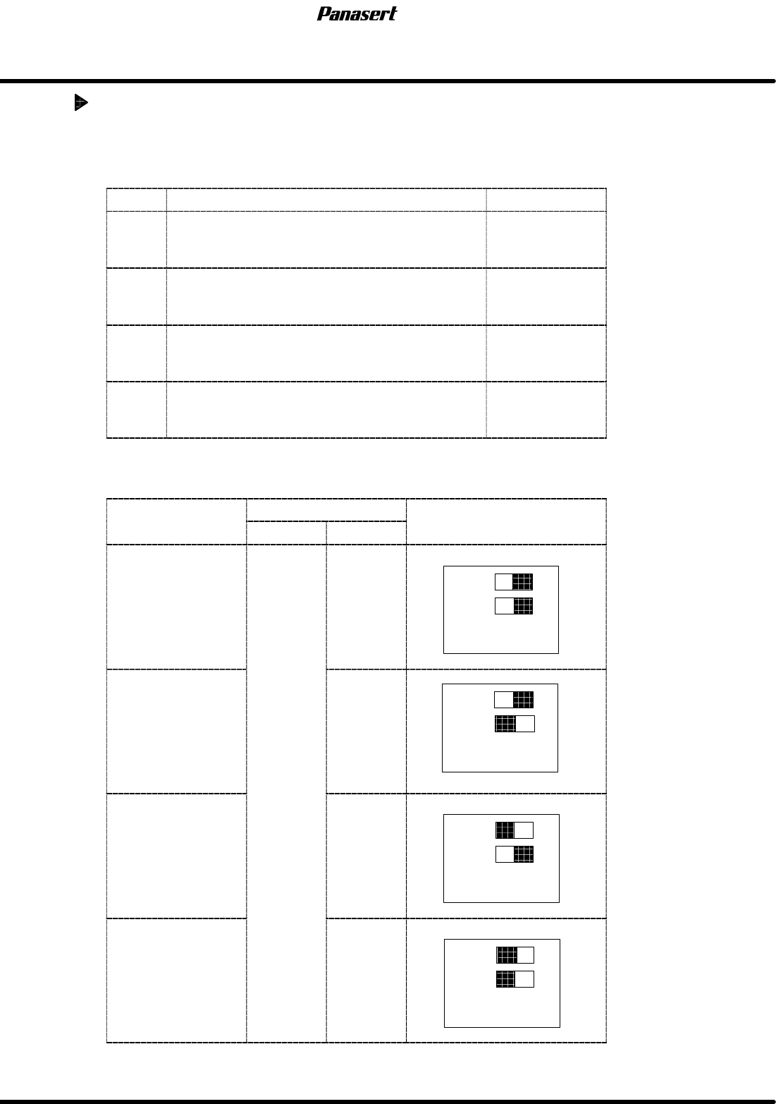
Driver loop and axis number
Axis
name
Optical loop
Setting
A
x
i
s name
Loop Axis No.
S
e
tti
ng
CX axis 1
10
ADR1
ADR2
CY axis
1
2
10
ADR1
ADR2
ST axis
1
3
10
ADR1
ADR2
SST axis 4
10
ADR1
ADR2
5.1 AC Servo Gain Adjustment
SERVICE MANUAL
SPF
5.1−3
D54SEC−84−040−A0
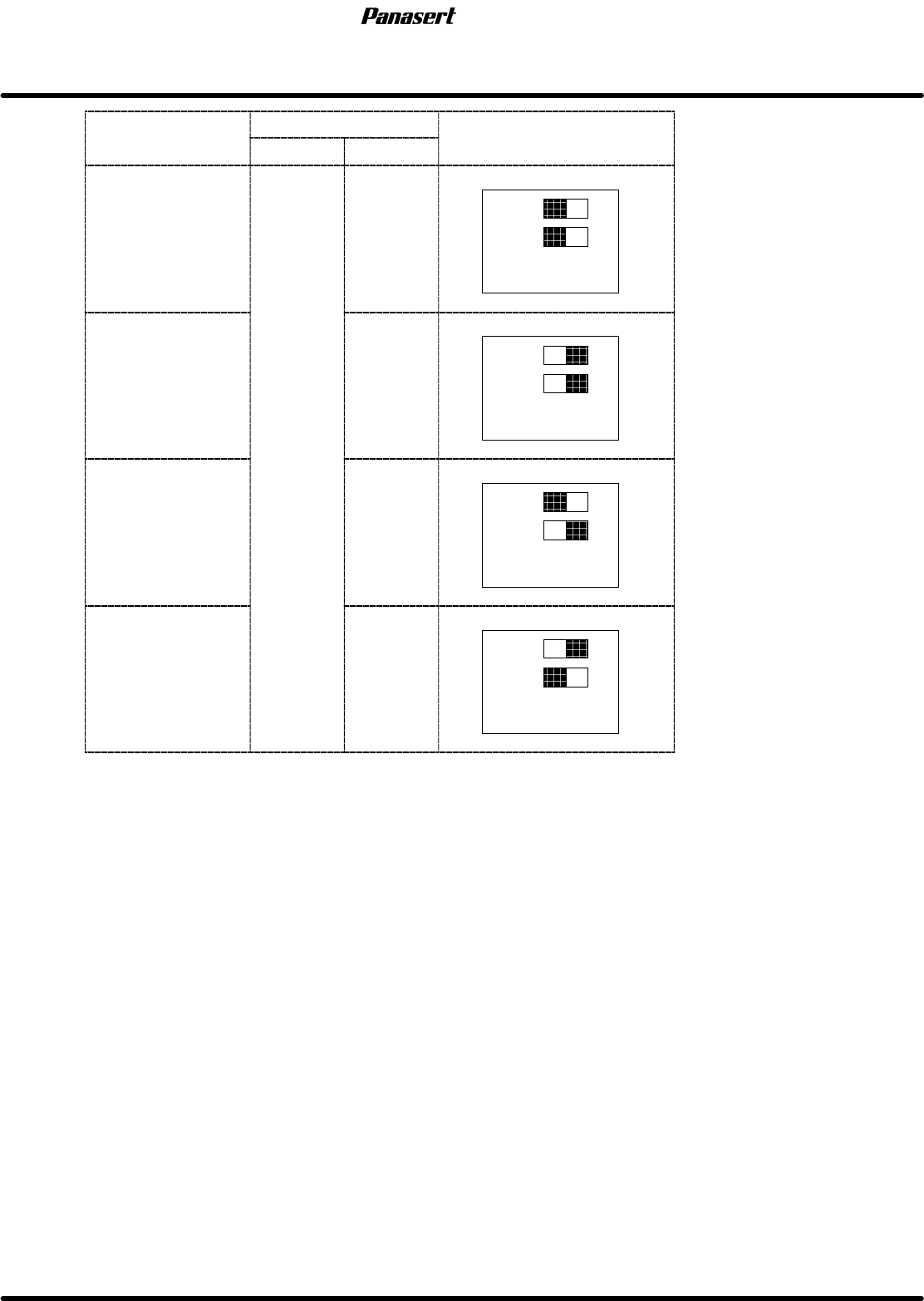
Axis
name
Optical loop
Setting
A
x
i
s name
Loop Axis No.
S
e
tti
ng
SQ axis 1
10
ADR1
ADR2
SCR axis
2
2
10
ADR1
ADR2
SY axis
2
3
10
ADR1
ADR2
SCX axis 4
10
ADR1
ADR2