SPF维修.pdf - 第94页
5.2 Software Upgrade Method SERVICE MANUAL SPF 5.2−1 D54SEC−84−320−A0 5.2 Software Upgrade Method D54SEC−84−320−A0 Sentence No. Software upgrade method MMC board (N1 J006B1) MMI board (N1 L1053F) SC board (N1 J016D1) MMC…
SPF
5.1 AC Servo Gain Adjustment
SERVICE MANUAL
5.1−6
D54SEC−84−040−A0
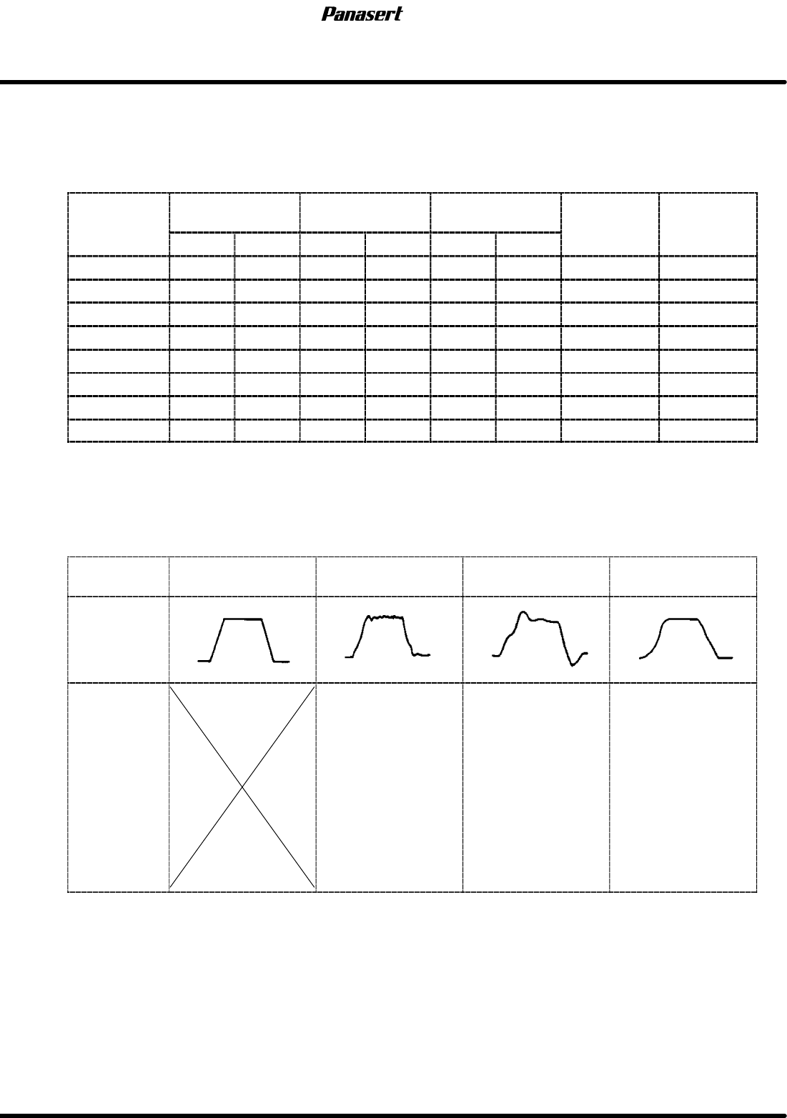
8. Check the the difference between the gain setting values and the standard values.
=REFERENCE=
Refer to following table.
AC servo driver standard gain settings
Gain
POSITIONAL
FEEDBACK
SPEED
FEEDBACK
INTEGRAL OF
SPEED
FEED
FOR
W
ARD
CHANGE
TIMING
Gain
1st 2nd 1st 2nd 1st 2nd
FOR
W
ARD
TIMING
CX axis 9 9 20 20 0 20 0 0
CY axis 8 8 13 13 0 20 0 0
ST axis 28 28 28 28 0 21 0 0
SST axis 12 12 9 9 0 20 0 0
SCR axis 5 4 3 2 0 20 0 0
SCX axis 4 3 4 3 0 5 0 0
SY axis 8 8 10 4 0 1 0 0
SQ axis 10 10 9 9 0 1 0 0
9. Adjust the gain setting values according to following table.
=CHECK=
The values of ’FEED FORWARD’ should be standard value.
Motor
condition
Ideal Noisy
Not smooth
movement
Bad positioning
precision
Wave
Adjustment
procedure
1. Reduce the
speed feedback.
2. Reduce the
integral of speed.
3. Reduce the
positional feedback.
1. Reduce the
positional feedback.
2. Reduce the
speed feedback.
3. Reduce the
integral of speed.
1. Reduce the
positional feedback.
2. Reduce the
speed feedback.
3. Reduce the
integral of speed.
10. Execute the program and check if the problem is solved.
11. If not, try several times.
5.2 Software Upgrade Method
SERVICE MANUAL
SPF
5.2−1
D54SEC−84−320−A0
5.2 Software Upgrade Method
D54SEC−84−320−A0
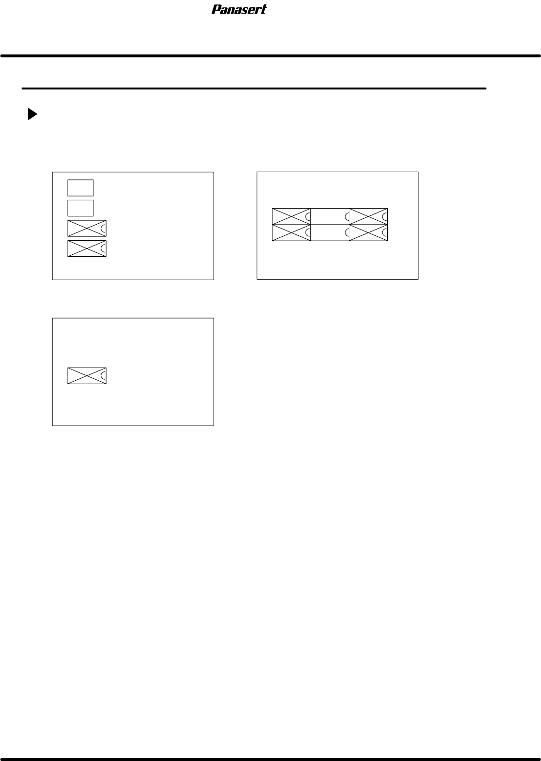
Sentence No.
Software upgrade method
MMC board (N1 J006B1)
MMI board (N1 L1053F)
SC board (N1 J016D1)
MMC ODD
MMC EVEN
SC
MMI
ODD2
MMI
ODD1
MMI
EVEN2
MMI
EVEN1
BOOT
EVEN
BOOT
ODD
ROM that needs to replace when upgrading the standard software
1. Save the all data.
2. Print out the machine data.
3. Print out the secret screen data.
=REFERENCE=
Referto’RELATEDINFORMATION/SecretScreenServiceFunctions(CONFIDENTIAL)’inthis
manual.
4. Initialize the RAM area.
5. Turn the power [OFF].
6. Disconnect the sub control panel and the printer.
7. Remove the cover of the Panadac 783.
8. Remove the MMC board, MMI board and SC board in order.
=HINT=
All the PCBs are tightened with screws per a PCB.
Be sure to remove PCB with pulling the white lever endways after loosening the screws
completely.
The screws can’t pull out from the PCB.

SPF
5.2 Software Upgrade Method
SERVICE MANUAL
5.2−2
D54SEC−84−320−A0
9. Remove the designated ROM to replace.
=CHECK=
Be careful the electrostatics and the bend of the ROM legs.
10. Attach the SC board, MMI board and MMC board in order.
=CHECK=
Be careful the bend of the ROM legs.
11. Check that the ROM legs are inserted completely and tighten the screws.
12. Connect the sub control panel and the printer.
13. Turn the power [ON] and return to origin.
14. Initializes the RAM area.
15. Load the all data.
16. Check the machine data and the secret screen data.