SPF维修.pdf - 第82页
4.6 Others SERVICE MANUAL SPF 4.6−1 D54SEC−W0−900−A0 4.6 Others D54SEC−W0−900−A0 Sentence No. 4.6.1 CL Axis (Cleaner) Origin Adjustment Unit No. CL Axis (Cleaner) Origin Adjustment CL axis (cleaner) origin adjustment 1. …
SPF
4.5 Upper Section Unit : Others
SERVICE MANUAL
4.5−6
D54SEC−W1−V00−B0
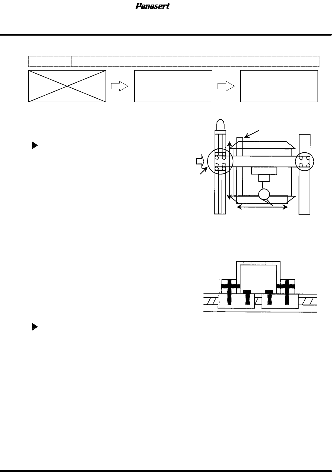
4.5.4 CX Axis and CY Axis Squareness Adjustment
Unit No.
CX Axis and CY Axis
Squareness Adjustment
4.5.3 CY Axis Origin Adjustment
4.5.2 CX Axis Origin Adjustment
=Preparation=
1. Square
2. Dial gauge
3. Magnet stand
CX axis squareness adjustment
1. Turn the power [ON] and return to origin.
2. Set the square so that it becomes parallel to CY
axis on the table.
=HINT=
Be sure to fix the square with the magnet
stand so that it does not move.
3. Attach the magnet stand to the camera axis
frame.
4. Touch the dial gauge to the point A on the
square.
5. Zero the dial gauge.
6. Check the parallelism of X direction (between A
to B).
=Specification=
Squareness : Within 0.03mm
7. If not within the specification, loosen the joint
bolts of the ball screw.
8. Tighten the one of the joint bolts temporarily.
9. Move the camera axis and tighten the rest of the
joint bolts with checking the parallelism.
10. Check the squareness again.
CY axis squareness adjustment
1. Do the same adjustment as the CX axis.
CY axis
Square
Camera axis
Joint
bolts
Measurement
A
B
0
0
A
Detailed view of A
4.6 Others
SERVICE MANUAL
SPF
4.6−1
D54SEC−W0−900−A0
4.6 Others
D54SEC−W0−900−A0
Sentence No.
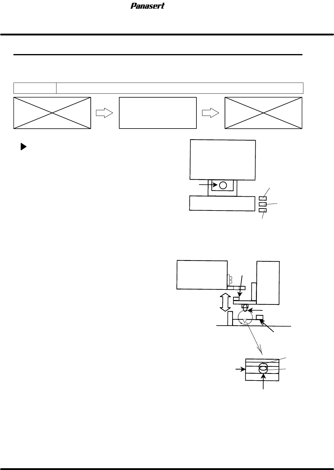
4.6.1 CL Axis (Cleaner) Origin Adjustment
Unit No.
CL Axis (Cleaner) Origin
Adjustment
CL axis (cleaner) origin adjustment
1. Turn the power [ON] and return to origin.
2. Turn “CLEANER” on the sub control panel [ON /
OFF].
=CHECK=
Make sure that the cleaner joint pin moves
up/down.
3. Check that the joint pin goes in the bracket hole
on the stage side smoothly.
=HINT=
If the air is cut, it can check easily.
4. Check that the ball plunger goes in the center of
the bracket groove when the joint pin lowers.
5. If not, move the bracket of the main body side to
adjust the position.
6. Check that the joint pin goes in the bracket hole
on the stage side smoothly again.
7. Check that the origin sensor and other sensors
detect correctly.
8. Check that the origin sensor detects its origin
when the cleaner unit is moved slightly back and
forth by hands.
Stage
Joint pin
Ball plunger
Cleaner
Fixed bolt
OK
Head ascend
prohibition
Cleaner
origin
Cleaner area
Joint pin
Cleaner
NG
Groove
Stage
Ball plunger
SPF
4.6 Others
SERVICE MANUAL
4.6−2
D54SEC−W0−900−A0
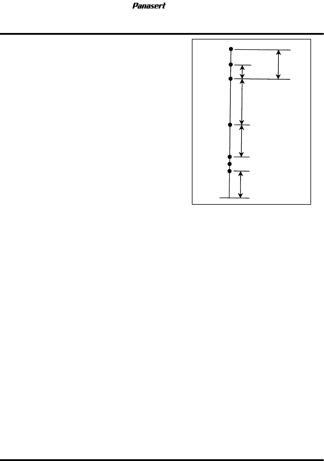
9. Check the limit sensors.
Ascend
prohibition
Valid stroke
Cleaning area (579
)
80±1
Area sensor
Ascend prohibition
−798.5±1
−780
0
−2
−744±1
−165±1
0
−2
Origin
−1
+1
0
−2
Stroke related diagram