SPF维修.pdf - 第70页
4.3 Upper Section Positioning Related Matter SERVICE MANUAL SPF 4.3−5 D54SEC−W1−000−B0 10. Check the ( ± ) limit sensors. =Specification= (+) safety limit : 363 ± 0.5mm (+) limit : 361 ± 0.5mm (−) limit : −361 ± 0.5mm (−…
SPF
4.3 Upper Section Positioning Related Matter
SERVICE MANUAL
4.3−4
D54SEC−W1−000−B0
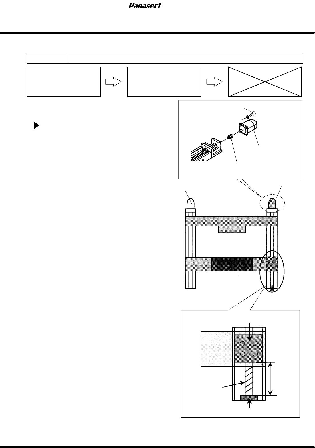
4.3.3 SQ Axis (Squeegee Y Axis) Origin Adjustment
Unit No. 1080807100,1080807150
SQ Axis (Squeegee Y Axis)
Origin Adjsutment
4.3.2 SQ Axis (Squeegee Y Axis)
Motor Replacement
=Preparation=
1. Scale
SQ axis origin adjustment
1. Turn the power [ON] and return to origin.
2. Turn “SERVO MOTOR” on the main control panel
[OFF].
3. Check the distance from the mechanical stopper
to the end face of the slider with the scale.
=Specification=
Distance : 365mm
4. If not within the specification, loosen the N
coupling on the ball screw side with the spanner.
5. Adjust the distance with rotating the ball screw.
6. Tighten the N coupling with the spanner.
7. Turn “SERVO MOTOR” on the main control panel
[ON].
8. Return to origin.
9. Check that the origin sensor detects correctly.
SQ axis motor
Squeegee
Slider
Mechanical
stopper
CY axis motor
365mm
Ball screw
SQ axis motor
Motor bolt
N coupling
Camera
Mechanical stopper
4.3 Upper Section Positioning Related Matter
SERVICE MANUAL
SPF
4.3−5
D54SEC−W1−000−B0
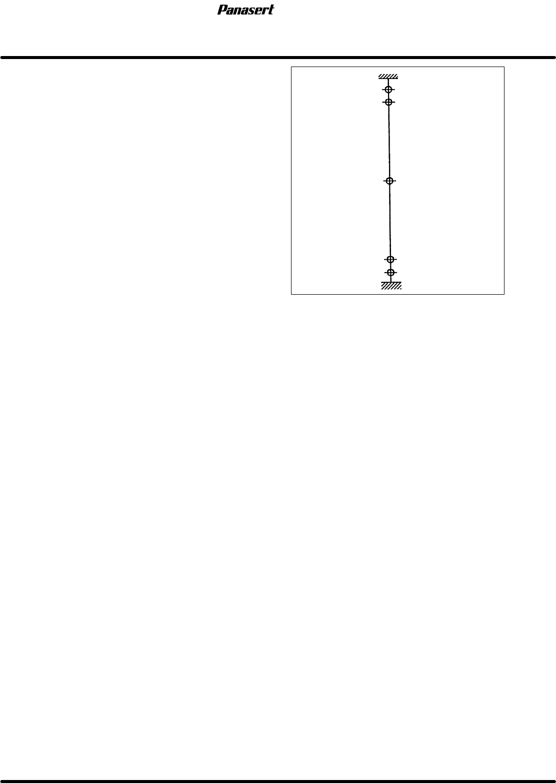
10. Check the (±) limit sensors.
=Specification=
(+) safety limit : 363±0.5mm
(+) limit : 361±0.5mm
(−) limit : −361±0.5mm
(−) safety limit : −363±0.5mm
+365
+363
+361
0
−361
−365
Mechanical stopper
(+) limit
Origin
(−) safety limit
Mechanical stopper
(At CY axis origin)
Stroke related diagram
−363
(−) limit
(+) safety limit
SPF
4.3 Upper Section Positioning Related Matter
SERVICE MANUAL
4.3−6
D54SEC−W1−000−B0
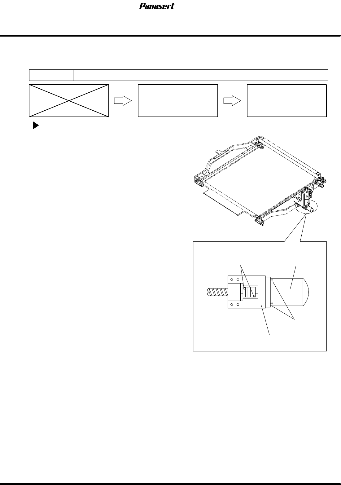
4.3.4 SCX Axis (Screen Compensated Axis) Motor
Replacement
Unit No. 1080810100
SCX Axis (Screen
Compensated Axis) Motor
Replacement
4.3.1 SCX Axis (Screen
Compensated Axis) Origin
Adjustment
SCX axis motor replacement
1. Turn the power [ON] and return to origin.
2. Turn the power [OFF].
3. Disconnect the motor connectors.
4. Loosen the coupling bolt on the motor side.
=CHECK=
Be sure to detach the motor shaft and the
coupling completely.
5. Remove the motor bolt and remove the motor
from the motor bracket.
6. Replace the motor.
7. Tighten the motor bolt and coupling bolt.
8. Connect the motor connectors.
Motor
Motor bolts
Coupling bolts
Motor bracket