SPF维修.pdf - 第60页
Slow Origin (+) mechanical stopper (−) mechanical stopper (−) limit 15 798.5 0 (+) limit 790 785 −10 −5 −15.5 (+) safety limit (−) safety limit Stroke related diagram Slow range 4.2 Lower Section Unit : Others SERVICE MA…
Stage
Fixed rail guide
Reference mark
OK
NG
Position error
Stage Y axis motor
Coupling
Coupling bolt
Motor bolt
Reference mark
Stage Y axis motor
SPF
4.2 Lower Section Unit : Others
SERVICE MANUAL
4.2−6
D54SEC−W4−600−B0
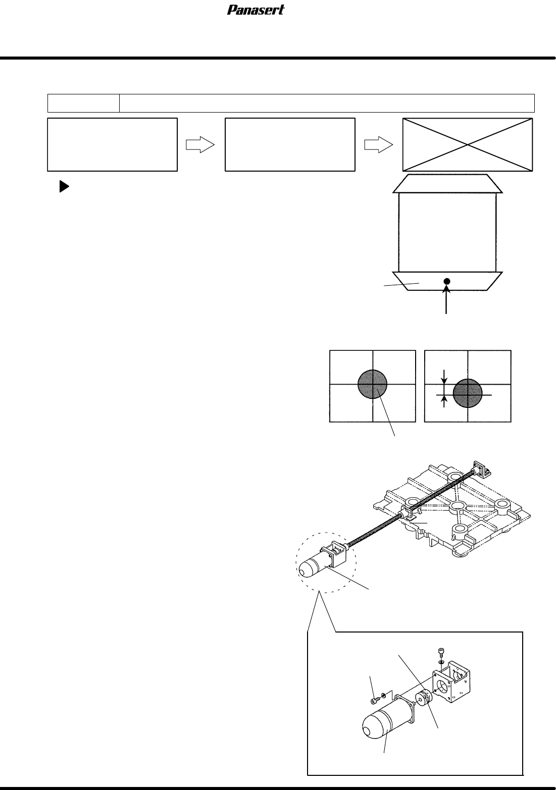
4.2.4 SY Axis (Stage Y Axis) Origin Adjustment
Unit No. 1080804200
SY Axis (Stage Y Axis) Origin
Adjustment
4.2.1 SY Axis (Stage Y Axis)
Motor Replacement
SY axis origin adjustment
1. Turn the power [ON] and return to origin.
2. Move the SY axis (stage Y axis) to 150mm.
3. Move the ST axis to 26mm.
4. Move the CY axis to 624.5mm.
5. Turn “RECOG LIGHT RING” on the sub control
panel [ON].
6. Check visually that the reference mark matches
with the center of the cross line on the monitor
screen.
7. If not, loosen the coupling bolt on the ball screw
side.
8. Rotate the ball screw while watching the monitor
screen until the reference mark matches with the
center of the cross line on the monitor screen.
9. Tighten the coupling bolt on the ball screw side.
10. Check that the sensor dog matches with the origin
sensor.
11. If not, move the sensor dog and the sensor until it
matches.
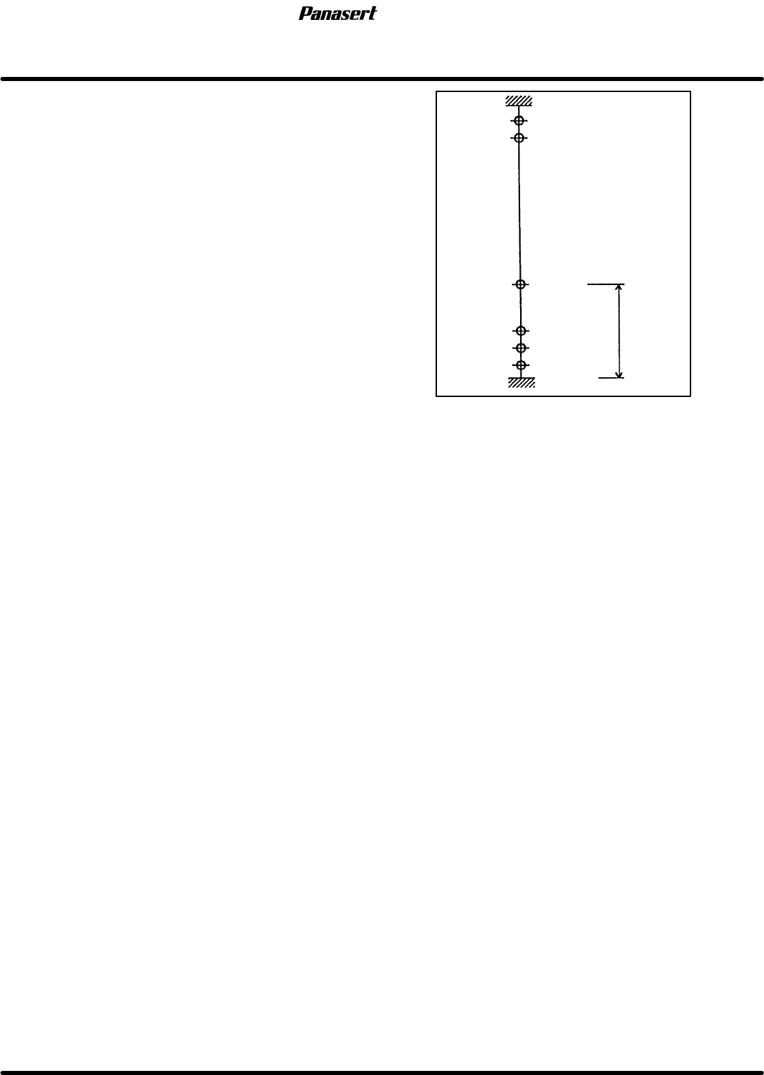
Slow
Origin
(+) mechanical stopper
(−) mechanical stopper
(−) limit
15
798.5
0
(+) limit
790
785
−10
−5
−15.5
(+) safety limit
(−) safety limit
Stroke related diagram
Slow range
4.2 Lower Section Unit : Others
SERVICE MANUAL
SPF
4.2−7
D54SEC−W4−600−B0
12. Check the (±) limit sensors.
=Specification=
(+) safety limit : 790±2mm
(+) limit : 785±1mm
Slow limit : 15 ±1mm
(−) limit : −5±1mm
(−) safety limit : −10±2mm
SPF
4.2 Lower Section Unit : Others
SERVICE MANUAL
4.2−8
D54SEC−W4−600−B0
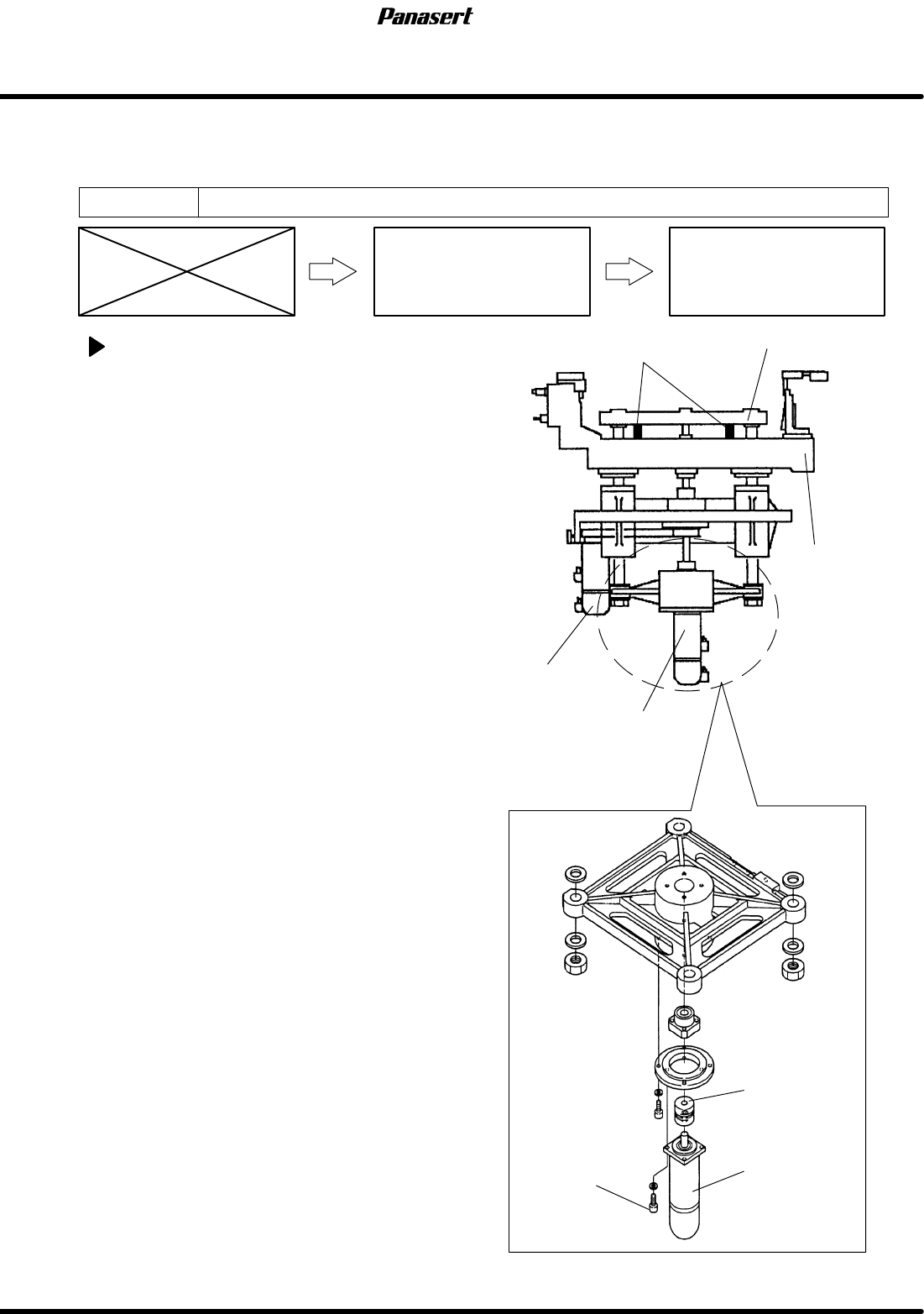
4.2.5 SST Axis (Support Plate Up/Down Axis) Motor
Replacement
Unit No. 1080804300
SST Axis (Support Plate
Up/Down Axis) Motor
Replacement
4.2.6 SST Axis (Support Plate
Up/Down Axis) Height
Adjustment
SST axis motor replacement
1. Turn the power [ON] and return to origin.
2. Turn the power [OFF] and insert the stoppers
between the sub stage table and the support plate
frame.
=CHECK=
Support plate frame lowers if the coupling bolt
on the motor side is loosened.
3. Remove the rear lower side cover.
=CHECK=
Make sure that the coupling can be seen
from the rear left side.
4. Disconnect the motor connectors.
5. Loosen the coupling bolt on the motor side.
6. Remove the motor bolt and the motor.
7. Replace the motor.
8. Tighten the the coupling bolt on the motor side.
9. Tighten the motor bolt.
10. Connect the motor connectors.
Motor bolt
Motor
Coupling
Sub stage table
Support
plate
frame
ST axis motor
SST axis motor
Stoppers