SPF维修.pdf - 第90页
5.1 AC Servo Gain Adjustment SERVICE MANUAL SPF 5.1−3 D54SEC−84−040−A0 Axis name Optical loop Setting A x i s name Loop Axis No. S e tti ng SQ axis 1 10 ADR1 ADR2 SCR axis 2 2 10 ADR1 ADR2 SY axis 2 3 10 ADR1 ADR2 SCX ax…
SPF
5.1 AC Servo Gain Adjustment
SERVICE MANUAL
5.1−2
D54SEC−84−040−A0
AC servo driver dip switch setting
Switch setting
Switch setting is as the following tables.
No.
Specification Setting
SW1
Position loop gain
ON : Gain setting range high gain
OFF : Gain setting range low gain
OFF
SW2
Speed loop gain
ON : Gain setting range high gain
OFF : Gain setting range low gain
OFF
SW3
Speed monitor output
ON : 127kpps / 2.5V
OFF : 5000rpm / 2.5V
OFF
SW4
Speed monitor output
ON : 2500 pulses / 2.5V
OFF : 100rpm / 2.5V
OFF
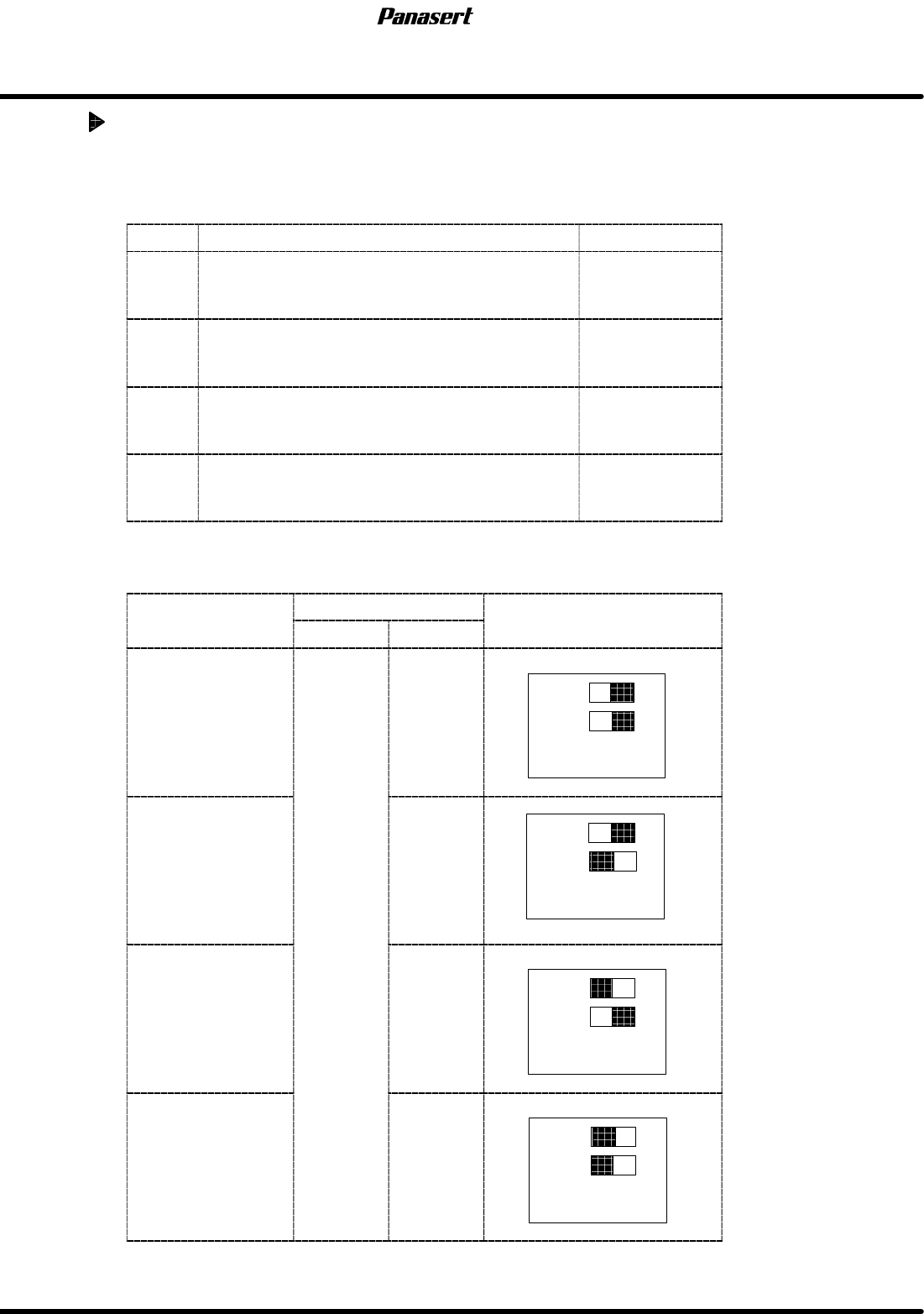
Driver loop and axis number
Axis
name
Optical loop
Setting
A
x
i
s name
Loop Axis No.
S
e
tti
ng
CX axis 1
10
ADR1
ADR2
CY axis
1
2
10
ADR1
ADR2
ST axis
1
3
10
ADR1
ADR2
SST axis 4
10
ADR1
ADR2
5.1 AC Servo Gain Adjustment
SERVICE MANUAL
SPF
5.1−3
D54SEC−84−040−A0
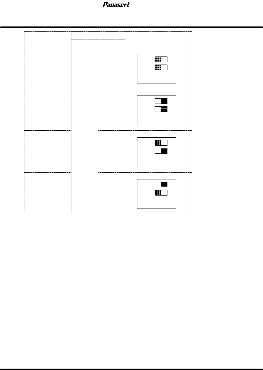
Axis
name
Optical loop
Setting
A
x
i
s name
Loop Axis No.
S
e
tti
ng
SQ axis 1
10
ADR1
ADR2
SCR axis
2
2
10
ADR1
ADR2
SY axis
2
3
10
ADR1
ADR2
SCX axis 4
10
ADR1
ADR2
SPF
5.1 AC Servo Gain Adjustment
SERVICE MANUAL
5.1−4
D54SEC−84−040−A0
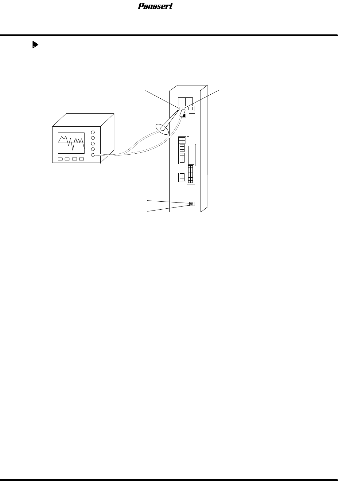
AC servo gain adjustment
1. Supply the power to the oscilloscope from the other machines except SPF.
2. Attach oscilloscope probe to ’PERM’ and ’GND’ of the motor driver monitor terminal.
PERM GND
ADR2
ADR1
Oscilloscope
3. Select a program.
=HINT=
Any programs can be used under the normal conditions.
4. Execute the program in the aging mode and check the AC servo driver wave and servo motor
condition using the oscilloscope.
5. Select “F1” (MACHINE INITIAL SETTINGS) ® “F7” ® “SHIFT” ® “S” ® “P” ® “SHIFT” ® “F”
from the main control panel.