SPF维修.pdf - 第63页
SPF 4.2 Lower Section Unit : Others SERVICE MANUAL 4.2−10 D54SEC−W4−600−B0 15. Rotate the ball screw to adjust. =HINT= Adjust the gap with touching the dial gauge to the support height adjustment jig before loosening the…
4.2 Lower Section Unit : Others
SERVICE MANUAL
SPF
4.2−9
D54SEC−W4−600−B0
4.2.6 SST Axis (Support Plate Up/Down Axis) Height
Adjustment
Unit No.
SST Axis (Support Plate
Up/Down Axis) Height
Adjustment
Maintenance Manual /
MAINTENANCE GUIDE / Fixed
Rail Guide Parallelism
Adjustment
Maintenance Manual /
MAINTENANCE GUIDE / Fixed
and Movable Rail Guide
Coplanarity Adjustment
=Preparation=
1. Dial gauge
2. Magnet stand
3. Support height adjustment jig (55.9mm)
SST axis height adjustment
1. Turn the power [ON] and return to origin.
2. Set the rail width to 250mm.
3. Move the SY axis (stage Y axis) to
150mm.
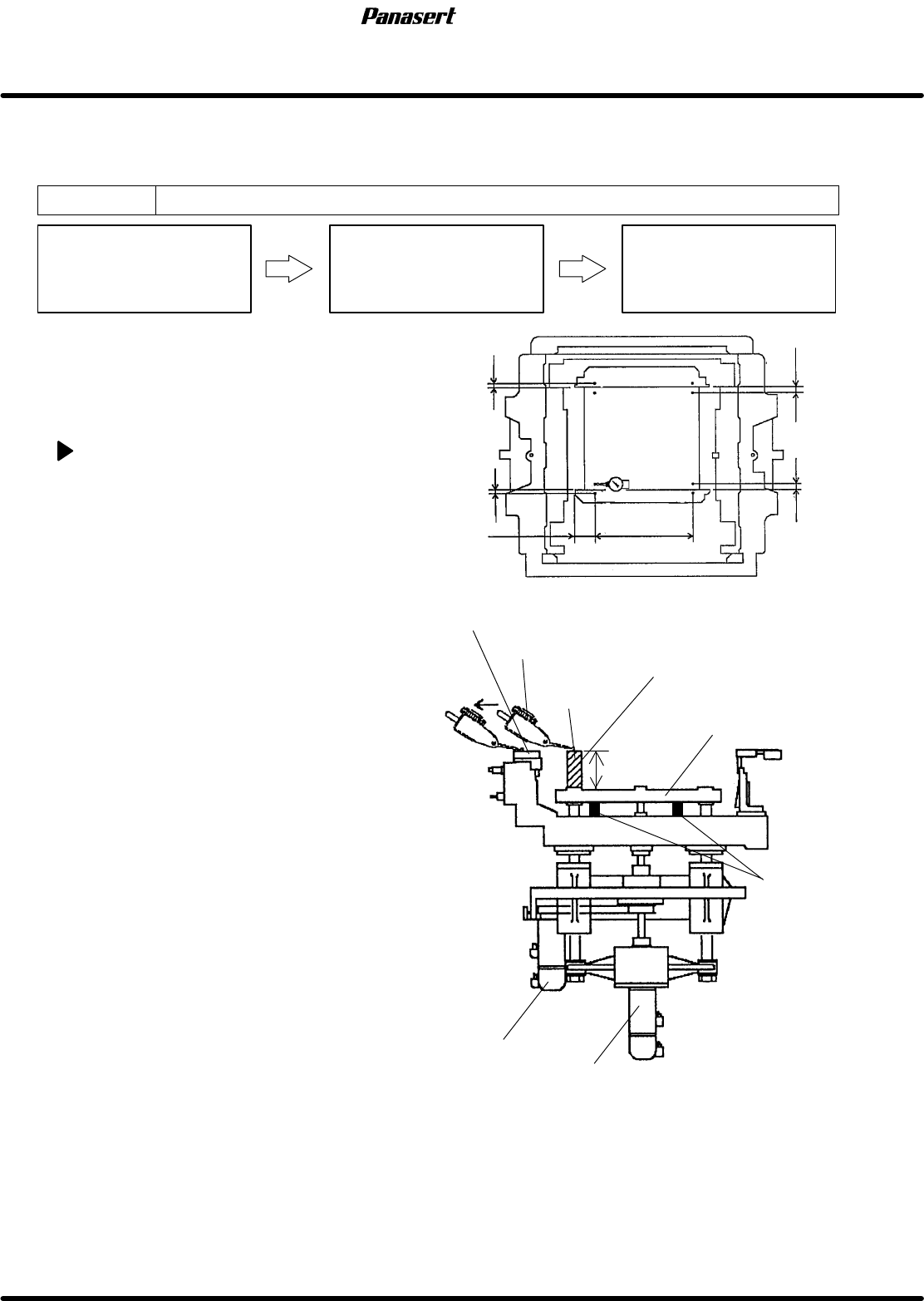
4. Set the support height adjustment jig on
the sub stage table.
5. Attach the magnet stand to the CX axis
frame.
6. Touch the dial gauge to the support height
adjustment jig.
7. Zero the dial gauge.
8. Move the CY axis in NC AXIS JOG
CHECK and touch the dial gauge to the
upper surface point A on the fixed rail
guide.
9. Check the gap of the the upper surface
point A on the fixed rail guide and the
support height adjustment jig plate frame.
10. In the same way, check the gap of b−B,
c−C and d−D.
=Specification=
Gap : Within ± 0.05mm
11. If not within the specification, remove the
rear cover.
12. Move the sub stage table to rear.
13. Insert the stoppers between the sub stage
table and the support plate frame.
=CHECK=
Sub stage table lowers if the coupling
bolt on the motor side is loosened.
14. Loosen the coupling bolt on the motor side.
Sub stage table
Support height adjustment jig
Dial gauge
Support plate frame
Reference 0
ST axis motor
SST axis motor
Stoppers
Ref. 0
ba
c
B
D
d
Ref. 0
Ref. 0
Ref. 0
C
A
4mm
2mm
60mm
480mm
15mm
15mm
FIxed rail guide
55.9mm
SPF
4.2 Lower Section Unit : Others
SERVICE MANUAL
4.2−10
D54SEC−W4−600−B0
15. Rotate the ball screw to adjust.
=HINT=
Adjust the gap with touching the dial gauge to
the support height adjustment jig before
loosening the coupling bolt.
16. Tighten the coupling bolt on the motor side.
17. Check the gap again.
18. Attach the rear cover.
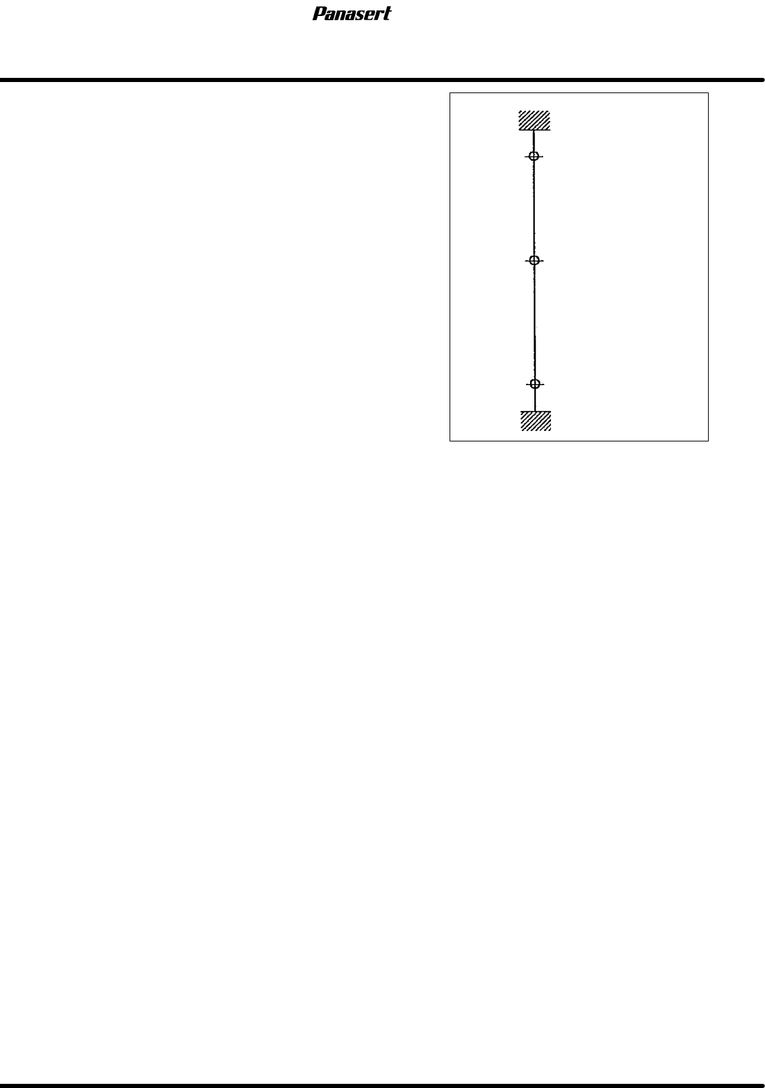
19. Check the (±) limit sensors.
=Specification=
(+) limit : 25.5±0.5mm
(−) limit : −29±0.5mm
Mechanical stopper
(+) limit
Mechanical stopper
(−) limit
Origin (5mm under PCB )
27.5
25.5
0
−29
−31
Stroke related diagram
4.2 Lower Section Unit : Others
SERVICE MANUAL
SPF
4.2−11
D54SEC−W4−600−B0
4.2.7 Support Plate Coplanarity Adjustment
Unit No. 1080804300
Support Plate Coplanarity
Adjustment
Maintenance Manual /
MAINTENANCE GUIDE / Fixed
and Movable Rail Guide
Coplanarity Adjustment
=Preparation=
1. Maximum PCB
2. (−) driver
3. Dial gauge
4. Magnet stand
5. Support height adjustment jig
Support plate coplanarity adjustment
1. Turn the power [ON] and return to origin.
2. Move the movable rail to the width of the
maximum PCB.
3. Move the SY axis (stage Y axis) to 150mm.
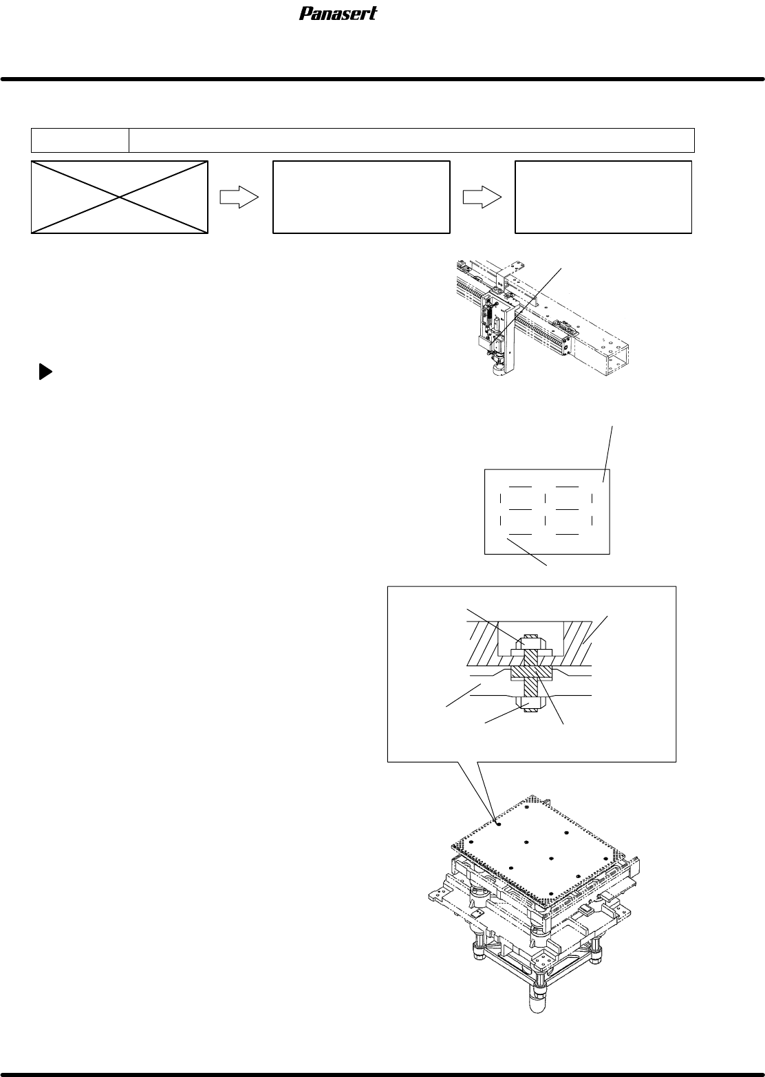
4. Set the support height adjustment jig at the point
A on the support plate.
5. Attach the magnet stand to the camera axis
frame.
6. Touch the dial gauge to the support height
adjustment jig upper surface.
7. Zero the dial gauge.
8. Move the support height adjustment jig at the
point B on the support plate.
9. Check the coplanarity of the support height
adjustment jig upper surface.
=CHECK=
Be sure to check the coplanarity of the point
C to the point I.
=Specification=
Coplanarity : Within 0.1mm
10. If not within the specification, remove the nut (J)
of the adjustment bolt to remove the support
plate.
11. Check the coplanarity of the adjustment bolts (4
pcs.).
=Specification=
Coplanarity : Within 0.1mm
12. If not within the specification, loosen the nut
(K) and adjust the coplanarity with using the (−)
driver.
13. Tighten the nut (K).
G
C
F
I
B
E
H
A
D
Reference 0
Adjustment bolt
Nut (K)
Nut (J)
Frame
Support plate
Support plate
Camera axis frame