TR7600 SIII_Camera_Calibration_en_v_2_0_2.pdf - 第25页
Test Research, Inc. TR7600 SIII Ser ies User G uide – Cam era Calibr ation 19 4) Put the center of the cross line at the center of the two white square holes in both X a nd Y direction. Figure 23 : Center A li gnment Cal…
Test Research, Inc.
18 TR7600 SIII Series User Guide – Camera Calibration
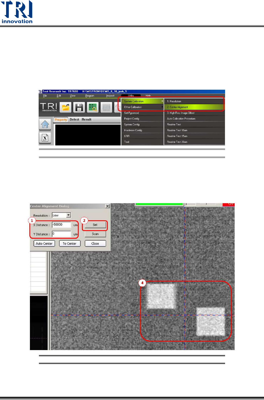
2.3 Center Alignment Calibration
Note: Generally, this calibration is not required. Please check with TRI FAEs before
performing this calibration. Without professional assistance, calibration that failed
may cause issues which are difficult to resolve.
Go to [Utility] [System Calibration ] [Center Alignment]
Figure 21: Utility/System Calibration/Center Alignment
Only calibrate for the low resolution by following procedure below.
1) Key in -50000 and 0 respectively in X Distance and Y Distance dialog boxes.
2) Click [Set].
Figure 22: Center Alignment Calibration Steps
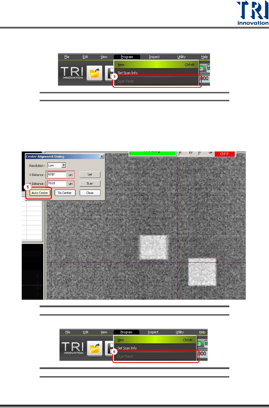
3) Go to [Program] and press [Scan Panel].
Test Research, Inc.
TR7600 SIII Series User Guide – Camera Calibration 19
4) Put the center of the cross line at the center of the two white square holes in both X and
Y direction.
Figure 23: Center Alignment Calibration Step 4
5) Click “Auto Center”. After doing this, the values in the X and Y Distance dialogues will
change.
6) Go to [Program] and press [Scan Panel] again. Then two white square holes should
have overlapped in some areas.
Figure 24: Center Alignment Calibration Steps
Figure 25: Center Alignment Calibration Step 6
Test Research, Inc.
20 TR7600 SIII Series User Guide – Camera Calibration
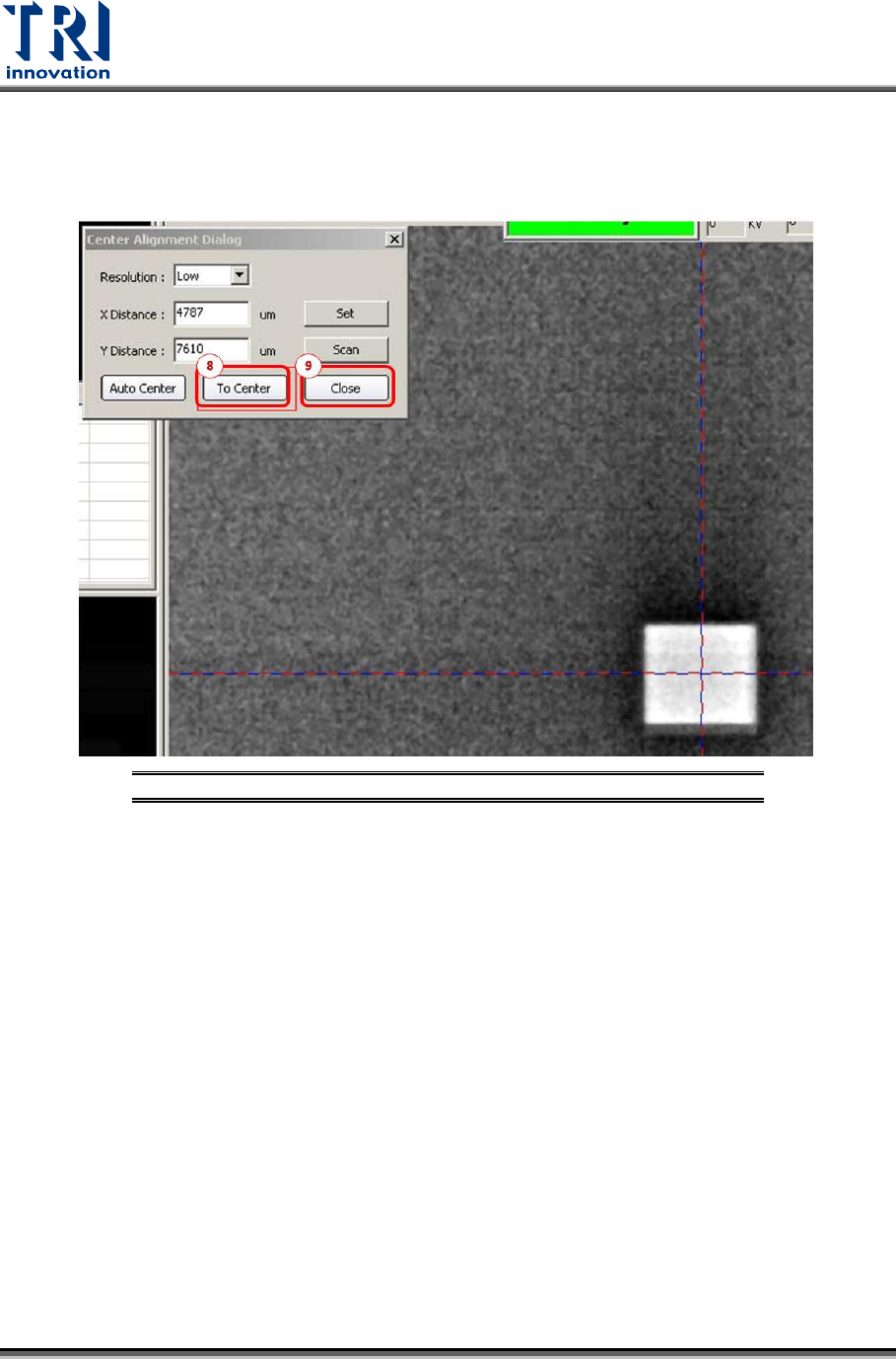
7) Put the center of the cross line at the center of the upper white hole.
8) Press [To Center] and two white square holes should have overlapped in most areas.
9) Click [Close] to complete this calibration.
Figure 26: Center Alignment Calibration Steps