TR7600 SIII_Camera_Calibration_en_v_2_0_2.pdf - 第68页
Test Research, Inc. 62 TR7600 SI II Series User Guide – Camera Ca libration 3.10 Zero Shift In this calibration, put the calibration board into the machine m anually and clamp it. In this w ay, when the front door is o…
Test Research, Inc.
TR7600 SIII Series User Guide – Camera Calibration 61
12) Click on [Move To]. The spot of Laser Sensor0 will be moved to the square hole
causing the spot unable to be seen.
13) Go to the machine, if the spot of Laser Sensor0 does not move into the the
square hole, use the [
↑], [↓], [←], or [→] buttons to move the spot into the square
hole manually.
Figure 115: Move the Laser Spot into the Square Hole
14) Click on [Set Pos].
15) Click on [Go] and [Save] to save the data. It may take few minutes to save the
data. Meanwhile, Laser Sensors may move around to calculate the data needed
automatically.
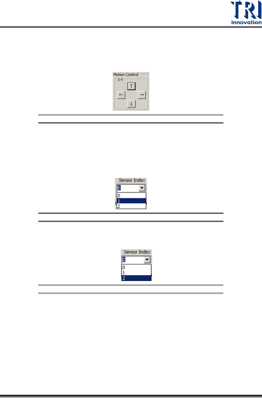
16) Choose [1] in the [Sensor Index] field and repeat from step 4 to step 15 above.
Figure 116: Choose Laser Sensor 1
17) Choose [2] in the [Sensor Index] field and repeat from step 4 to step 15 above.
Figure 117: Choose Laser Sensor 2
Test Research, Inc.
62 TR7600 SIII Series User Guide – Camera Calibration
3.10 Zero Shift
In this calibration, put the calibration board into the machine manually and
clamp it. In this way, when the front door is opened and amplifiers are set
up, the calibration board can be held and the zero height of its top surface
can be fixed.
This step is used to set up the zero height for 3 amplifiers.
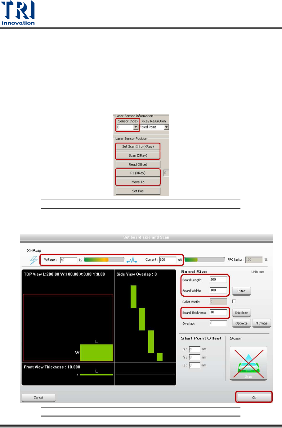
1) Click on [Laser Offset].
2) In order to set up Laser Sensor0, choose [0] in the [Sensor Index] field.
Figure 118: Laser Sensor
3) Click [Set Scan Info(XRay)]. Set up the scan parameters and click on [OK].
Figure 119: Set Up Scan Parameters
Test Research, Inc.
TR7600 SIII Series User Guide – Camera Calibration 63
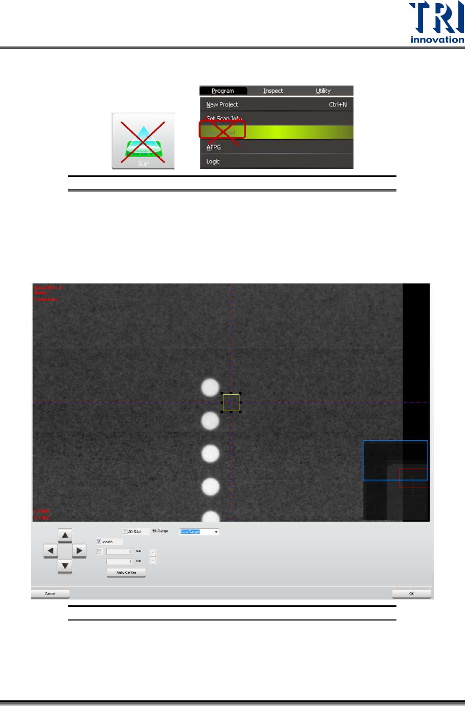
4) Click on [Scan (XRay)]. Do not use the [Scan] buttons shown as below to scan
the board.
Figure 120: Don’t Use These Buttons to Scan the Board
5) Click on [(P1(XRay))]. Move the box to one column circles closely, but still keep
the box on the metal surface, so amplifiers can record the metal surface as zero
height. Click on [ok] to save the box coordinates. You only have to assign the box
position once, and Laser Sensor0, Laser Sensor1, and Laser Sensor2 can move
to this box position later.
Figure 121: Move the Box Close to One Column Circles
6) Click on [Move To] and then sensor0 will move to the assigned place. Go to the
machine and check if the spot of Laser Sensor0 is moved to one column circles
closely.