TR7600 SIII_Camera_Calibration_en_v_2_0_2.pdf - 第82页
Test Research, Inc. 76 TR7600 SI II Series User Guide – Camera Ca libration Figure 155: Choose L aser Senso r 0 16) Click on [Set Scan Info(XRay )] to set up the scan paramaters and click on [OK]. Figure 15 6: Set Scan I…
Test Research, Inc.
TR7600 SIII Series User Guide – Camera Calibration 75
12) When the laser intensity value is stable, click [Live] again.
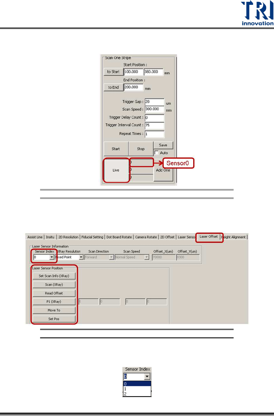
13) Record the laser intensity value, Value A, from the [Sensor0] field.
Figure 153: Record the Value in the Laser Sensor0 Field
14) Please repeat the steps above and record the laser intensity value in position B.
Click on [Laser Offset].
Figure 154: Laser Offset
15) Choose [0] in the [Sensor Index] field.
Test Research, Inc.
76 TR7600 SIII Series User Guide – Camera Calibration
Figure 155: Choose Laser Sensor 0
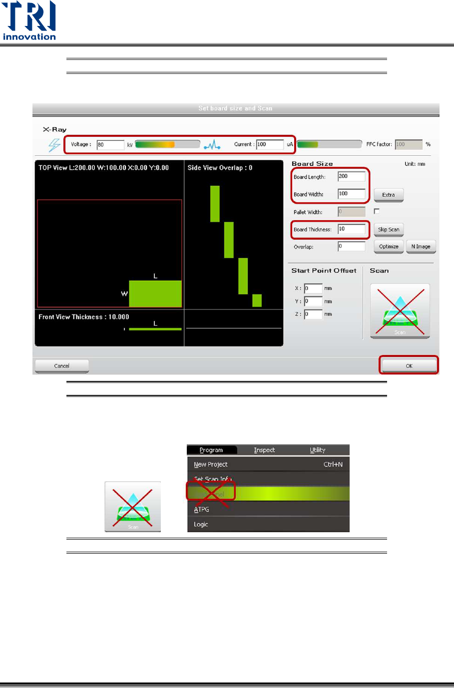
16) Click on [Set Scan Info(XRay)] to set up the scan paramaters and click on [OK].
Figure 156: Set Scan Info
17) Do not use the [Scan] buttons shown as below to scan the board.
Figure 157: Don’t Use These Buttons to Scan the Board
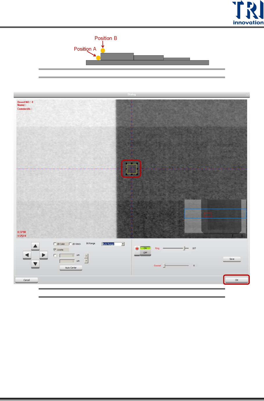
18) Click on [Scan (XRay)] to scan the board.
19) Click on [P1(XRay)].
20) Move the box to position B. Do not put the box too close to the fault, or the laser
point may be moved to the fault that will result in a wrong height calculation.
However, the closer position A and position B, the higher the accuracy.
Test Research, Inc.
TR7600 SIII Series User Guide – Camera Calibration 77
Figure 158: Position A and Position B
Figure 159: Move the Box to Position B
21) Click on [OK] to save position B coordinates.
22) Click on [Move To] and Laser Sensor0 will move to the assigned position.
23) Click on [Laser Sensor].
24) Click on [Live] to read the laser intensity value.
25) When the laser intensity value is stable, click [Live] again.
26) Record the laser intensity value, Value B, from the [Sensor0] field.