TR7600 SIII_Camera_Calibration_en_v_2_0_2.pdf - 第80页
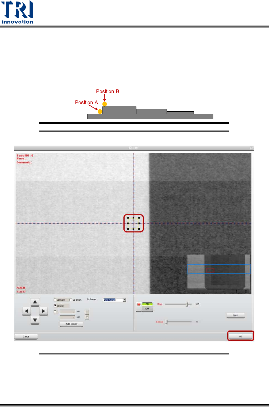
Test Research, Inc. 74 TR7600 SI II Series User Guide – Camera Ca libration 5) Click on [Scan (XRay)] to scan the board. 6) Click on [P1(XRay)]. 7) Move the box to position A that is on t he b oard top s urface. Do not p…
Test Research, Inc.
TR7600 SIII Series User Guide – Camera Calibration 73
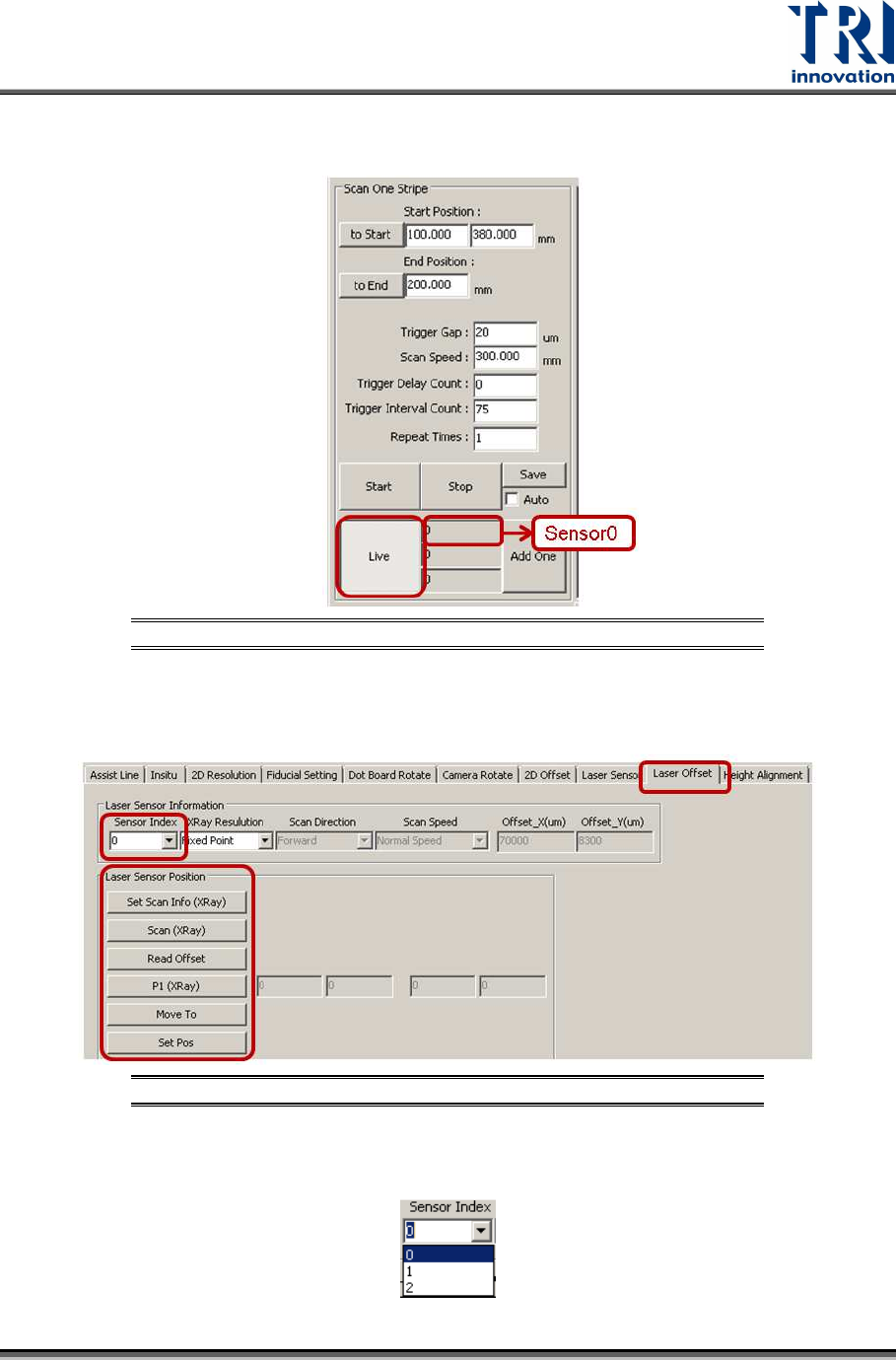
2) Choose [0] in the [Sensor Index] field.
Figure 148: Choose Laser Sensor 0
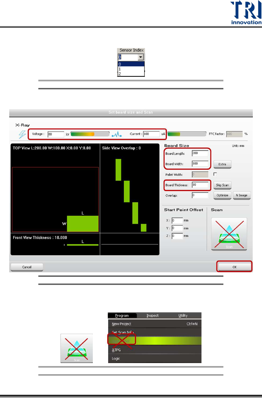
3) Click on [Set Scan Info(XRay)] to set up the scan paramaters and click on [OK].
Figure 149: Set Scan Info.
4) Do not use the [Scan] buttons shown as below to scan the board.
Figure 150: Don’t Use These Buttons to Scan the Board
Test Research, Inc.
74 TR7600 SIII Series User Guide – Camera Calibration
5) Click on [Scan (XRay)] to scan the board.
6) Click on [P1(XRay)].
7) Move the box to position A that is on the board top surface. Do not put the box
too close to the fault, or the laser point may be moved to the fault that will result in
a wrong height calculation. However, the closer position A and position B, the
higher the accuracy.
Figure 151: Position A and Position B
Figure 152: Move the Box to Position A
8) Click on [OK] to save position A coordinates.
9) Click on [Move To] and Laser Sensor0 will move to the assigned position.
10) Click on [Laser Sensor].
11) Click on [Live] to read the laser intensity value.
Test Research, Inc.
TR7600 SIII Series User Guide – Camera Calibration 75
12) When the laser intensity value is stable, click [Live] again.
13) Record the laser intensity value, Value A, from the [Sensor0] field.
Figure 153: Record the Value in the Laser Sensor0 Field
14) Please repeat the steps above and record the laser intensity value in position B.
Click on [Laser Offset].
Figure 154: Laser Offset
15) Choose [0] in the [Sensor Index] field.