TR7600 SIII_Camera_Calibration_en_v_2_0_2.pdf - 第74页
Test Research, Inc. 68 TR7600 SI II Series User Guide – Camera Ca libration 5) Click on [Scan (XRay)] t o scan the board and the m ain pr ogram will calculate the data needed. 6) Click on [P1(XRay)]. 7) Move the box to o…
Test Research, Inc.
TR7600 SIII Series User Guide – Camera Calibration 67
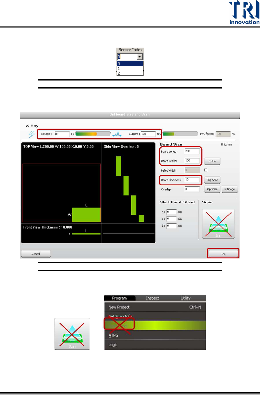
2) Choose [0] in the [Sensor Index] field.
Figure 129: Choose Laser Sensor 0
3) Click on [Set Scan Info(XRay)] to set up the scan paramaters and click on [OK].
Figure 130: Set Scan Info
4) Please don’t use the [Scan] buttons shown as below to scan the board.
Figure 131: Don’t Use These Buttons to Scan the Board
Test Research, Inc.
68 TR7600 SIII Series User Guide – Camera Calibration
5) Click on [Scan (XRay)] to scan the board and the main program will calculate the
data needed.
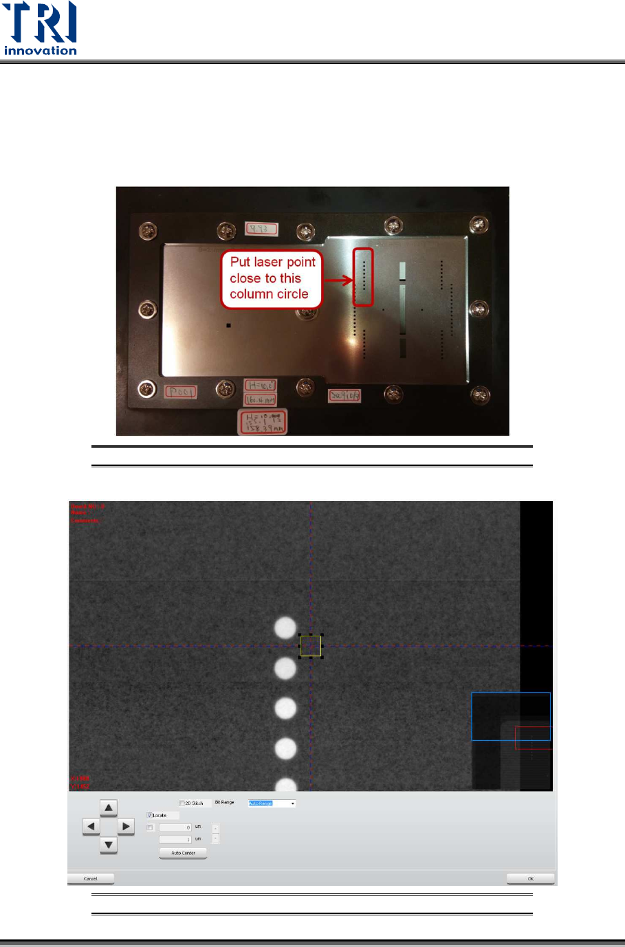
6) Click on [P1(XRay)].
7) Move the box to one column circles closely, but still keep the box on the metal
surface, so amplifiers can record the metal surface as zero height.
8) Click on [OK] to save the box coordinates.
Figure 132: Use this Column Circles for Calibration
Figure 133: Move the Box Close to One Column Circles
Test Research, Inc.
TR7600 SIII Series User Guide – Camera Calibration 69
9) Click on [Move To] and the spot of Laser Sensor0 will move to the assigned
position.
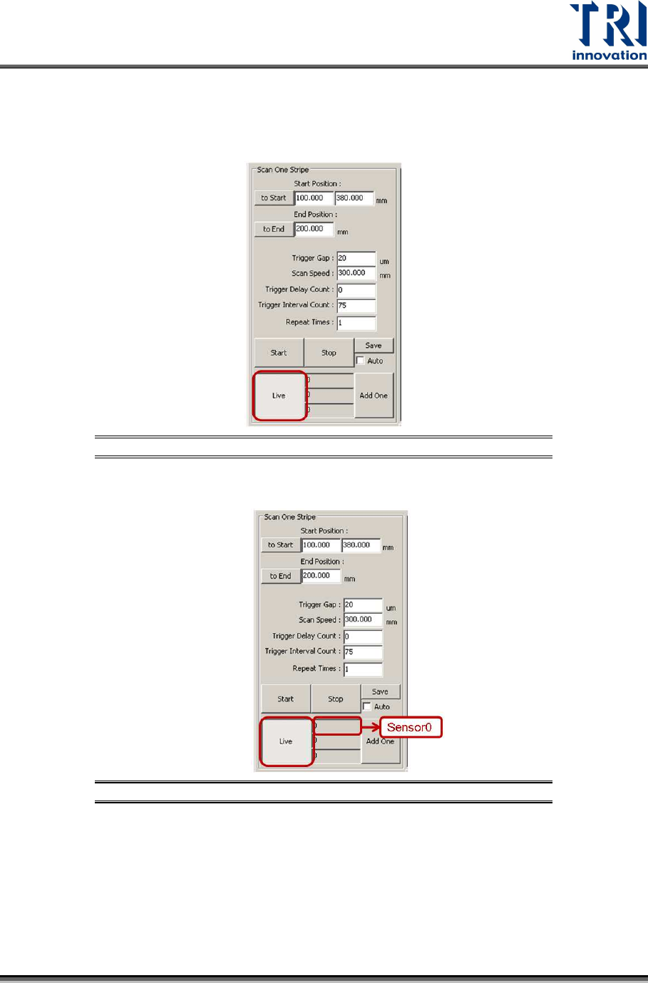
10) Click on [Laser Sensor].
11) Click on [Live] to read the laser intensity value.
Figure 134: Live
12) When the laser intensity value is stable, click [Live] again.
Figure 135: Record the Value in the Laser Sensor0 Field
13) Double-click on Center Position0 registry.
14) Read the laser intensity value from the [Sensor0] field, fill it in Center Position0
registry and click [Save]. This value should be very close to 0.