TR7600 SIII_Camera_Calibration_en_v_2_0_2.pdf - 第63页
Test Research, Inc. TR7600 SIII Ser ies User G uide – Cam era Calibr ation 57 5) Click on [ ←] or [→] button to set the mode as [S hift]. Figure 104: Shift 6) T he wi ndow should display the value [0.000]. Figure 105: 0.…
Test Research, Inc.
56 TR7600 SIII Series User Guide – Camera Calibration
Set Up the Tolerance Value
1) Click on [
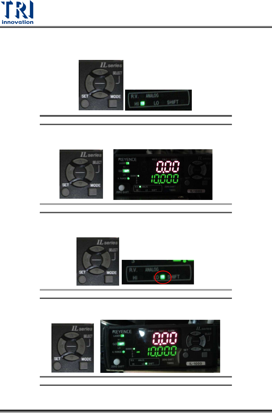
←] or [→] button to switch the mode to [HI].
Figure 100: HI
2) Click on [↑] or [↓] button to set the value as 10.
Figure 101: 10
3) Click on [
←] or [→] button to set the mode as [LO].
Figure 102: LO
4) Click on [↑] or [↓] button to set the value as [-10].
Figure 103: -10
Test Research, Inc.
TR7600 SIII Series User Guide – Camera Calibration 57
5)
Click on [
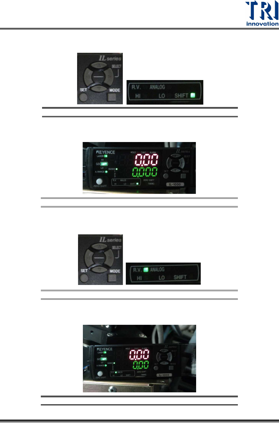
←] or [→] button to set the mode as [Shift].
Figure 104: Shift
6) The window should display the value [0.000].
Figure 105: 0.000
7) Click on [
←] or [→] button to set the mode as [R.V.].
Figure 106: RV
8) The setup is finished.
Figure 107: The Setup Is Finished

Test Research, Inc.
58 TR7600 SIII Series User Guide – Camera Calibration
3.9 Laser Offset
Uses the square hole’s position as a reference to tell laser about its position.
1) Put the calibration board into the machine.
Figure 108: Calibration Board
2) Click on [Laser Offset].
Figure 109: Laser Offset
3) Choose [0] in the [Sensor Index] field.
Figure 110: Choose Laser Sensor 0