TR7600 SIII_Camera_Calibration_en_v_2_0_2.pdf - 第65页
Test Research, Inc. TR7600 SIII Ser ies User G uide – Cam era Calibr ation 59 4) Click on [Set Scan Info(XRay)] to set up the scan paramaters and click on [OK]. Figure 111: Set Scan In fo. 5) Do not use the [Scan] button…

Test Research, Inc.
58 TR7600 SIII Series User Guide – Camera Calibration
3.9 Laser Offset
Uses the square hole’s position as a reference to tell laser about its position.
1) Put the calibration board into the machine.
Figure 108: Calibration Board
2) Click on [Laser Offset].
Figure 109: Laser Offset
3) Choose [0] in the [Sensor Index] field.
Figure 110: Choose Laser Sensor 0
Test Research, Inc.
TR7600 SIII Series User Guide – Camera Calibration 59
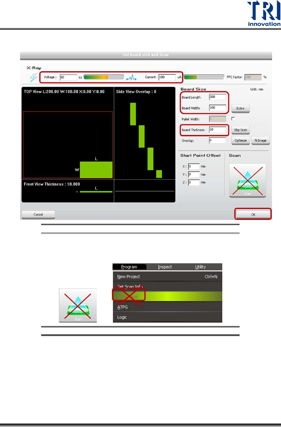
4) Click on [Set Scan Info(XRay)] to set up the scan paramaters and click on [OK].
Figure 111: Set Scan Info.
5) Do not use the [Scan] buttons shown as below to scan the board.
Figure 112: Don’t Use These Buttons to Scan the Board
6) Click on [Scan (XRay)] to scan the board and the main program will calculate the
required data.
Test Research, Inc.
60 TR7600 SIII Series User Guide – Camera Calibration
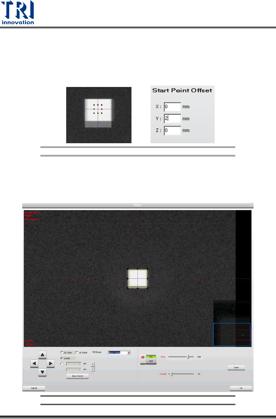
7) Click on [P1(XRay)].
8) Try to find a square in the figure. If Center Alignment calibration result is not very
good, two squares could be observed in the figure.To improve the result
accuracy, click on [Set Scan Info(XRay)] again and input 2 or 3 mm in the Y
Offset field. By doing so, these squares should be moved to the stripe center.
Click [OK].
Figure 113: Try Different X and Y Offset
9) Click on [Scan(XRay)] to scan the board again.
10) Click on [P1(XRay)].
11) Try to find a square in the figure. If only one square is observed in the figure, the
result is perfect. Please enlarge the box to confine this square and click on [OK].
Figure 114: Enlarge the Box to Confine the Square