00193697-01.pdf - 第15页
SIPLACE S oftware Guide SR.504.xx 3 Graphical user interface Issue 01/03 E N 3.2 Components of t he user in terface 15 3.2 Component s of the user interface 3 Fig. 3.2 - 1 Components of the user interface (for example, t…
3 Graphical user interface SIPLACE Software Guide SR.504.xx
3.1 Inputs and controls Issue 01/03 EN
14
3 Graphical user interface
This section describes how to use the various controls such as the keyboard, trackball, mouse
buttons and touch screen and also introduces the functions of the individual components of the
graphical user interface. 3
WARNING
In addition, the safety notes of the Operating instructions for SIPLACE HF take priority. 3
3.1 Inputs and controls
Keyboard 3
The keyboard with its integrated trackball and mouse buttons acts as the standard input tool for
the graphical user interface of the station computer software. 3
Trackball and mouse buttons 3
You use the trackball to move the mouse pointer across the user interface to the desired object
and then use the left mouse button to select the object or execute the appropriate function. 3
Touch screen 3
The (touch) screen can also be used to operate the user interface. In this way, you can directly
select the actions, or trigger the corresponding functions, by touching the corresponding object
with your finger on screen. 3
NOTE
In this guide, triggering an action using the left mouse button or by touching the screen with your
finger is always referred to as "clicking". 3
3
SIPLACE Software Guide SR.504.xx 3 Graphical user interface
Issue 01/03 EN 3.2 Components of the user interface
15
3.2 Components of the user interface
3
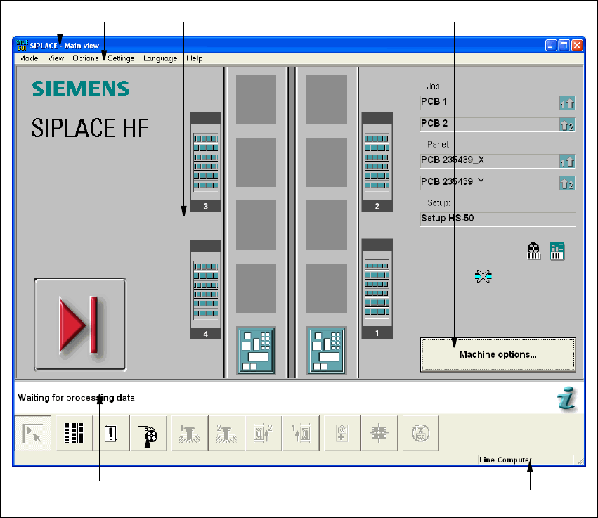
Fig. 3.2 - 1 Components of the user interface (for example, the Main view of the HF)
3
Key to Fig. 3.2 - 1
(1) Title bar
(2) Menu bar
(3) Working area/display area
(4) Controls
(5) Status area
(6) Toolbar
(7) Info bar
3
1
6
7
5
2 3 4
3 Graphical user interface SIPLACE Software Guide SR.504.xx
3.2 Components of the user interface Issue 01/03 EN
16
Title bar 3
The title bar displays the name of the current view (e.g. Main view). 3
Menu bar 3
The menu bar contains menus, the contents of which (functions and options available in the menu)
may change depending on the current view. 3
Working area/display area 3
This area displays the controls (buttons, icons) used to set/trigger functions, along with the con-
tents of active menus and submenus, general messages, error messages and other comments.
In addition, in the Main view, animated and/or different color objects may be used to indicate cer-
tain processes or statuses (e.g. processing, feeder location empty etc.). 3
Controls 3
You trigger actions, select options or make settings by clicking the corresponding controls with the
left mouse button.
If a control is displayed in inverse video (light gray), this means that the conditions for the execu-
tion of the corresponding functions are not satisfied. 3
Status area 3
The status area displays the current machine status, the last error to have occurred and the action
which is to be performed by the operator 3
Toolbar 3
This bar contains buttons which are used to switch the user interface to a different view where you
can then perform the necessary operations. 3
Clicking a button on the toolbar takes you to the view which corresponds to it. The button matching
the active view then itself becomes inactive. 3
Info bar 3
This bar displays concise information about the menu item or icon/button over which the mouse
pointer is currently positioned. The current control mode is displayed next to this in a separate
area. 3
If the "GEM Interface" option has been configured, the status of the connection to the host com-
puter is also displayed at the right-hand side of this area. 3