00193697-01.pdf - 第16页
3 Graphical user int erface SIPLACE Softw are Guide SR.504.xx 3.2 Components of the user interface Issue 01/03 EN 16 Title bar 3 The title ba r display s the name of the c urrent vi ew (e.g. M ain view ). 3 Menu bar 3 Th…
SIPLACE Software Guide SR.504.xx 3 Graphical user interface
Issue 01/03 EN 3.2 Components of the user interface
15
3.2 Components of the user interface
3
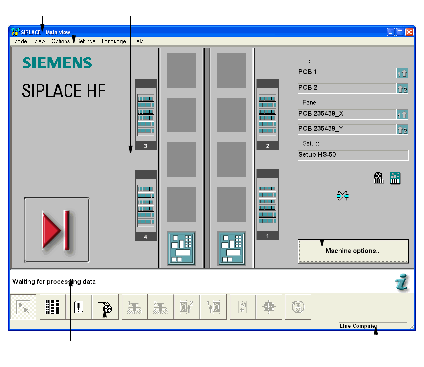
Fig. 3.2 - 1 Components of the user interface (for example, the Main view of the HF)
3
Key to Fig. 3.2 - 1
(1) Title bar
(2) Menu bar
(3) Working area/display area
(4) Controls
(5) Status area
(6) Toolbar
(7) Info bar
3
1
6
7
5
2 3 4
3 Graphical user interface SIPLACE Software Guide SR.504.xx
3.2 Components of the user interface Issue 01/03 EN
16
Title bar 3
The title bar displays the name of the current view (e.g. Main view). 3
Menu bar 3
The menu bar contains menus, the contents of which (functions and options available in the menu)
may change depending on the current view. 3
Working area/display area 3
This area displays the controls (buttons, icons) used to set/trigger functions, along with the con-
tents of active menus and submenus, general messages, error messages and other comments.
In addition, in the Main view, animated and/or different color objects may be used to indicate cer-
tain processes or statuses (e.g. processing, feeder location empty etc.). 3
Controls 3
You trigger actions, select options or make settings by clicking the corresponding controls with the
left mouse button.
If a control is displayed in inverse video (light gray), this means that the conditions for the execu-
tion of the corresponding functions are not satisfied. 3
Status area 3
The status area displays the current machine status, the last error to have occurred and the action
which is to be performed by the operator 3
Toolbar 3
This bar contains buttons which are used to switch the user interface to a different view where you
can then perform the necessary operations. 3
Clicking a button on the toolbar takes you to the view which corresponds to it. The button matching
the active view then itself becomes inactive. 3
Info bar 3
This bar displays concise information about the menu item or icon/button over which the mouse
pointer is currently positioned. The current control mode is displayed next to this in a separate
area. 3
If the "GEM Interface" option has been configured, the status of the connection to the host com-
puter is also displayed at the right-hand side of this area. 3

SIPLACE Software Guide SR.504.xx 3 Graphical user interface
Issue 01/03 EN 3.2 Components of the user interface
17
3.2.1 Icons in the working or display area
In main view, certain operating statuses (processing, error etc.) are indicated by different icons or
by changes in the color of the corresponding graphic in the display area. 3
Meaning of the Icons for the various different operating statuses 3
Machine power-up and reference run 3
When this icon is displayed, the majority of the functions of the machine cannot be operated. The
software is being loaded. Then the status field displays the status "Waiting for reference run" and
the action "Press start key". 3
Å Press the start key. The reference run is then performed.
After the reference run, the machine is ready to perform placement operations.
The following icon is then displayed.
3
Stop processing PCB 3
The machine is already running or is ready. 3
Click the button: The machine stops.
The icon changes to one shown below. This icon is then displayed until assembly of the PCBs in
the machine has been completed and these have been transported into the intermediate or output
conveyor, or in other words, until the processing conveyors have been emptied.
3
Shown after "Stop processing PCB" and while waiting for the processing
conveyors to be emptied 3
The machine is still placing components, but the stop button has already been activated. 3
Placement of the boards in processing conveyor 1 and 2 or the center conveyor will be completed
and these will be moved to the immediate or output conveyor. The machine will then be stopped.3
Click the button: The machine will continue without interruption. 3
(The triangle in the icon is continuously circled by a small yellow arrow.)
Once the processing areas have been emptied, the following icon is displayed. 3
3
3