00193697-01.pdf - 第85页
SIPLACE S oftware Guide SR.504.xx 8 New functionality in 504.01 Issue 01/03 E N 8.3 Matrix tray changer MTC2 85 8.3 Matrix tray ch anger MT C2 The MTC2 s upports the use of tr ays with flexible dimensi ons of up to 240 x…
8 New functionality in 504.01 SIPLACE Software Guide SR.504.xx
8.2 RV head nozzle changer Issue 01/03 EN
84
8.2 RV head nozzle changer
8.2.1 Nozzle changer for 6-nozzle head
The nozzle changer for a 6-nozzle head was adapted for the SIPLACE HF machine as follows:
The magazines have now been rotated by 90 degrees. This enables 6 magazines to fit on a single
bar. The software has not changed apart from the rotation of the 6-nozzle magazines and the
change in coordinates that results from this. 8
8.2.2 Nozzle changer for 12–nozzle head
The nozzle changer for the 12-nozzle head now has 5 magazines. These are mounted in the same
horizontal orientation as before,
and in each sector, if no MTC is mounted. The nozzles can be defined for each magazine on the
SIPLACE Pro computer in the normal manner. 8
SIPLACE Software Guide SR.504.xx 8 New functionality in 504.01
Issue 01/03 EN 8.3 Matrix tray changer MTC2
85
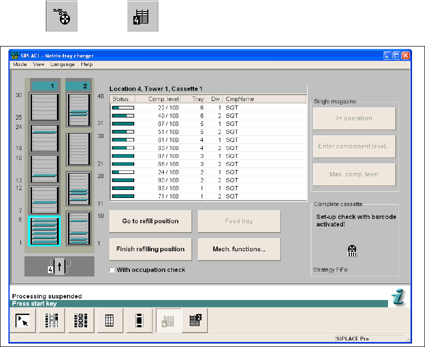
8.3 Matrix tray changer MTC2
The MTC2 supports the use of trays with flexible dimensions of up to 240 x 340 mm. The MTC2
is capable of accommodating 100 Jedec trays. 8
The MTC records the operating hours and the number of level changes for component provision
processes. This data can be called up in SITEST. 8
The 504.01 software has been adapted as follows. Tower 1 is wider and accommodates 5
magazines in each of the 6 levels. The functionality is unchanged. 8
8
The MTC functions can be called up using the
"Feeders" --> "MTC" view. 8
8
Fig. 8.3 - 1 "Matrix tray changer" view

8 New functionality in 504.01 SIPLACE Software Guide SR.504.xx
8.4 Synchronous dual conveyor with PCB barcode Issue 01/03 EN
86
8.4 Synchronous dual conveyor with PCB barcode
As of the 503.01 version of the software, the use of synchronous dual conveyors is supported.
The 504.01 version of the software now allows the use of synchronous dual conveyors with PCB
barcode operation. 8
When using dual conveyor machines the boards are moved asynchronously by default. Boards
are assembled alternately on conveyors 1 and 2. This means that the time required for transport
does not increase the overall length of the placement process. In this case, a panel correlates to
a single board. When using a synchronous conveyor system, a board is described across both
tracks. This board is thus made up of at least two subpanels and is referred to below as a "logical
board". 8
By default, the conveyor controller treats the conveyor tracks independently
of each other (asynchronous). Synchronous dual conveyor operation allows you to treat boards
traveling into the machine simultaneously on the two input conveyors as a single logical board.
This is intended to increase the throughput for panels that require different nozzle configurations.8
After they have been released for further transport, the physical boards are moved simultaneously
into the processing area and clamped. When they are moved onto the processing conveyor, the
specification is made as to whether the logical board consists of one or two physical boards. This
ensures that even single boards can be placed. 8
Then placement is started. After placement, the physical boards that make up a logical board are
released at the same time and are transferred to the next conveyor. 8
Further transportation of a logical board (consisting of one or more physical boards) to a
subsequent conveyor only takes place when the downstream conveyors for both tracks are empty.8
NOTE
Synchronous transport must be configured in the programming system and on the station using
SITEST. If the specifications of the programming system do not match the station configuration,
an error message is issued and the subsequent reference run will fail. 8