00193697-01.pdf - 第96页
8 New functionality in 504.01 SIPLACE Software Guide SR.504.xx 8.12 CAN interface modules Issue 01/03 EN 96 8.12 CAN interface modules The CAN inter face mod ules hav e been enh anced to include t he foll owing featu res…
SIPLACE Software Guide SR.504.xx 8 New functionality in 504.01
Issue 01/03 EN 8.11 Emergency mode - deactivate placement area
95
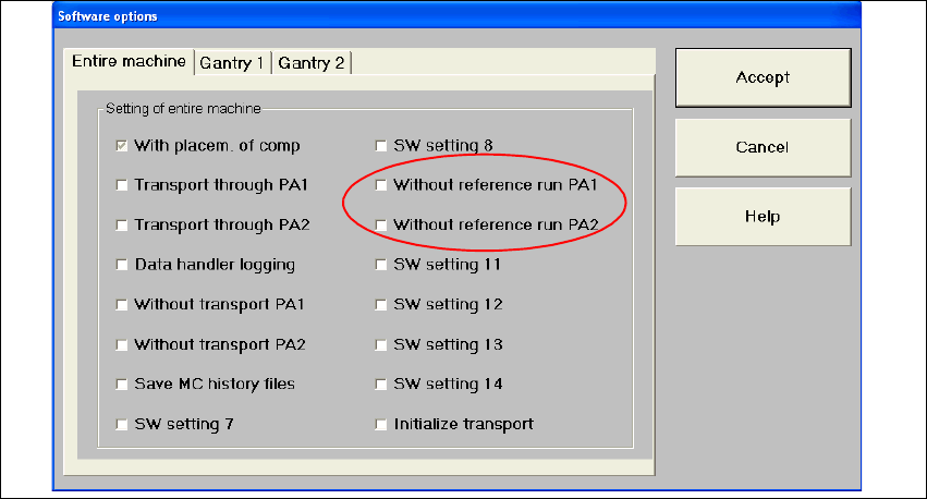
8.11 Emergency mode - deactivate placement area
An emergency mode has been implemented which allows you to deactivate a placement area.
This deactivated area then simply transports the boards through the machine. This means that the
gantries of this area are not referenced. 8
If both placement areas are deactivated, boards are simply transported through the entire
machine. (This differs from the "transport through" function that has already been implemented,
which requires a gantry reference run.) Transport errors are handled in the same manner as
before. 8
Activation and deactivation of the emergency mode has been realized using software options that
were already available. The "Entire machine" tab allows the operator to activate this option for
each of the placement areas before a reference run. 8
8
Fig. 8.11 - 1 Software options
Since this feature is designed for emergency operation, not all options are supported, in particular
not when reactivating the placement area. 8
8 New functionality in 504.01 SIPLACE Software Guide SR.504.xx
8.12 CAN interface modules Issue 01/03 EN
96
8.12 CAN interface modules
The CAN interface modules have been enhanced to include the following features: 8
– baud rate setting
– CAN-ID allocation
– Support for the platform III protocol
8.13 CAN/axis driver
The axis driver in the machine controller is responsible for communication with the axes. In the
SIPLACE HF, this interface has been changed from an SMP bus to a CAN bus. The protocol used
is the platform III protocol for subsystems on the CAN bus. 8
This means that no extra software version needs to be created in the axis firmware in order to map
the previous platform II protocol from the SDP bus to the CAN bus. The switch to CAN bus
interface means that the data structure of the axis firmware is also changed. 8
8.14 Barcode reader
8.14.1 Component barcode reader
In version 504 of the software you can use both the existing cabled barcode reader which is part
of component verification system or the SIPLACE Mobile Verifier (SMV). 8
Component verification can be called with View--> Setup. 8
8.14.2 PCB barcode reader
In version 504 of the software, both the existing barcode reader as well as the 2D barcode reader
can be used. 8
The dialog box "PCB barcode" can be called with Options --> PCB barcode.... 8
SIPLACE Software Guide SR.504.xx 8 New functionality in 504.01
Issue 01/03 EN 8.15 OIS
97
8.15 OIS
The software version OIS 2.2 supports the SIPLACE HF machine. 8
NOTE
A detailed description of the software option OIS 2.2 can be found in the instructions "Getting
started with OIS 2.2“ and the OIS 2.2 online Help system. 8
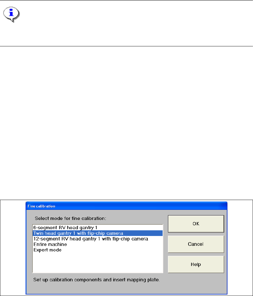
8.16 Fine calibration
The functionality has been enhanced compared with version 502 of the software and covers the
following Twin Head features: 8
– Placing and measuring an entire Twin Head panel (24 components per segment)
– Placing and measuring a single Twin Head segment panel (48 components per segment)
– A combination of the two scenarios above with any stationary component camera
– Recording and incorporation of segment-specific offsets for the Twin Head
– Used IC camera CC02-05, FC camera CC07-500
Fine calibration can be called with Options--> Fine calibration mode.... 8
8
Fig. 8.16 - 1 "Fine calibration" dialog box