00193697-01.pdf - 第40页
3 Graphical user int erface SIPLACE Softw are Guide SR.504.xx 3.3 User interf ace - views and menus Issue 01/03 EN 40 Å Click the Softwar e options menu ite m. The foll owing wind ow is ope ned. 3 Fig. 3.3 - 12 "Sof…
SIPLACE Software Guide SR.504.xx 3 Graphical user interface
Issue 01/03 EN 3.3 User interface - views and menus
39
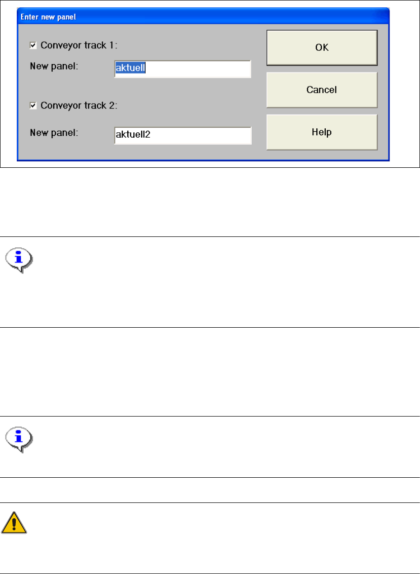
Å When using a dual conveyor, the following dialog appears:
3
Fig. 3.3 - 11 "Enter new panel" dialog box for dual conveyor
Å Now enter the name of the required panel in the displayed text box and click OK to confirm.
The panel data is now loaded.
NOTE
The data, including the fiducial and component package form data, of the last panel successfully
specified by SIPLACE Pro, is now saved on the station computer’s hard disk under the panel
name "AKTUELL" and can be loaded by entering this name. 3
Software options 3
This menu item is used to activate the test commands (test functions) for checking a variety of
machine components. 3
NOTE
This menu item can only be called from the "Service" access level. 3
WARNING
Settings for test commands and test command execution should be performed by service engi-
neers only. 3
3 Graphical user interface SIPLACE Software Guide SR.504.xx
3.3 User interface - views and menus Issue 01/03 EN
40
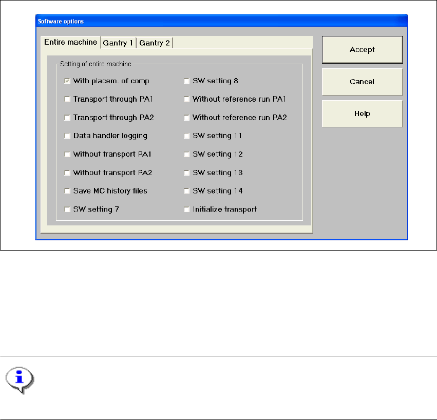
Å Click the Software options menu item.
The following window is opened.
3
Fig. 3.3 - 12 "Software options" dialog box (Example HF)
Å Select the tab corresponding to the required machine component and activate/deactivate the
test commands by clicking the corresponding checkboxes.
Å Click Accept to set the software options. The changes take effect with the next printed circuit
board.
NOTE
When the station is rebooted, the software options are reset to their original settings. 3

SIPLACE Software Guide SR.504.xx 3 Graphical user interface
Issue 01/03 EN 3.3 User interface - views and menus
41
Run options... Alt+t 3
This menu item can be used to switch the station to cycle mode (after pressing the stop button)
or to travel at reduced speed. This function can be used to localize errors. 3
Å Click the Run options... menu item or press the key combination ALT+t. The "Run options"
settings box is opened.
Å Check the Cycle mode box to activate cycle mode, or the Reduced speed box to travel at
reduced speed.
NOTE
In cycle mode, you must press the Start button on the machine for every operating step. 3
Video image PA1 > Alt+8 3
In the case of certain actions, it may be necessary to display the camera image of the machine
vision system (vision evaluation unit) on-screen during assembly. 3
Å Click the Video image PA1> menu item or press the key combination ALT+8. The display area
is switched to the MVS camera image in processing area 1.
Å Press the ESC key to restore the display area to the normal view.
Video image PA2 > Alt+9 3
Switch to the MVS camera image in processing area 2. 3
Fine calibration mode... 3
In "Stand alone" control mode, you can use this menu item to load the data of a selected panel
(placement program) from the station computer’s hard disk. 3
Å Please refer to the Fine Calibration User Manual and the online Help system for a detailed
description.
GEM default settings... 3
You use this item to specify the GEM parameters which are used as the default parameters when
the station is switched on. 3
Å Click the GEM default settings... menu item.
The window in which you set the GEM default parameters is now opened.