00193697-01.pdf - 第86页
8 New functionality in 504.01 SIPLACE Software Guide SR.504.xx 8.4 Synchronous dual conveyor with PCB ba rcode Issue 01/03 EN 86 8.4 Syn chronous dual convey or with PCB barcod e As of the 503.0 1 versio n of the so ftwa…
SIPLACE Software Guide SR.504.xx 8 New functionality in 504.01
Issue 01/03 EN 8.3 Matrix tray changer MTC2
85
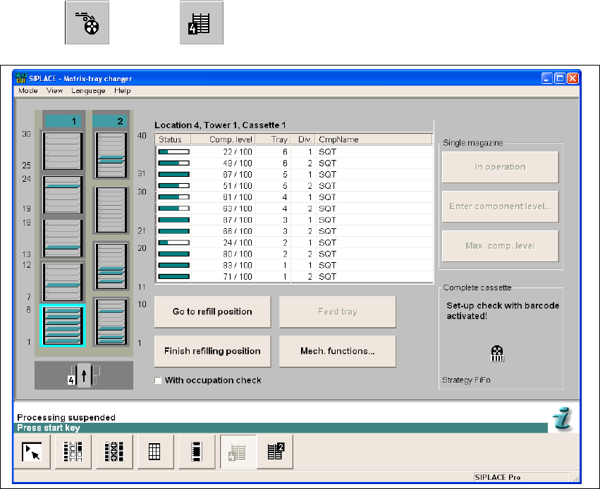
8.3 Matrix tray changer MTC2
The MTC2 supports the use of trays with flexible dimensions of up to 240 x 340 mm. The MTC2
is capable of accommodating 100 Jedec trays. 8
The MTC records the operating hours and the number of level changes for component provision
processes. This data can be called up in SITEST. 8
The 504.01 software has been adapted as follows. Tower 1 is wider and accommodates 5
magazines in each of the 6 levels. The functionality is unchanged. 8
8
The MTC functions can be called up using the
"Feeders" --> "MTC" view. 8
8
Fig. 8.3 - 1 "Matrix tray changer" view

8 New functionality in 504.01 SIPLACE Software Guide SR.504.xx
8.4 Synchronous dual conveyor with PCB barcode Issue 01/03 EN
86
8.4 Synchronous dual conveyor with PCB barcode
As of the 503.01 version of the software, the use of synchronous dual conveyors is supported.
The 504.01 version of the software now allows the use of synchronous dual conveyors with PCB
barcode operation. 8
When using dual conveyor machines the boards are moved asynchronously by default. Boards
are assembled alternately on conveyors 1 and 2. This means that the time required for transport
does not increase the overall length of the placement process. In this case, a panel correlates to
a single board. When using a synchronous conveyor system, a board is described across both
tracks. This board is thus made up of at least two subpanels and is referred to below as a "logical
board". 8
By default, the conveyor controller treats the conveyor tracks independently
of each other (asynchronous). Synchronous dual conveyor operation allows you to treat boards
traveling into the machine simultaneously on the two input conveyors as a single logical board.
This is intended to increase the throughput for panels that require different nozzle configurations.8
After they have been released for further transport, the physical boards are moved simultaneously
into the processing area and clamped. When they are moved onto the processing conveyor, the
specification is made as to whether the logical board consists of one or two physical boards. This
ensures that even single boards can be placed. 8
Then placement is started. After placement, the physical boards that make up a logical board are
released at the same time and are transferred to the next conveyor. 8
Further transportation of a logical board (consisting of one or more physical boards) to a
subsequent conveyor only takes place when the downstream conveyors for both tracks are empty.8
NOTE
Synchronous transport must be configured in the programming system and on the station using
SITEST. If the specifications of the programming system do not match the station configuration,
an error message is issued and the subsequent reference run will fail. 8
SIPLACE Software Guide SR.504.xx 8 New functionality in 504.01
Issue 01/03 EN 8.5 Component rejection
87
The following workflow/conditions also apply to PCB barcode operation: 8
– Each board has a barcode.
– The barcodes are read as the boards travel into the machine.
– Both barcodes are transmitted to the programming system which then selects the appropriate
recipe from the recipes configured. The panel information for this recipe is transmitted to the
station.
– If the programming system does not contain a recipe which is assigned to the barcodes that
have been read, the boards are simply transported through the machine.
– If the board has no barcode, or the barcode cannot be read, the station opens up
a dialog box and prompts the operator to enter a barcode by hand.
8.5 Component rejection
As of version 504 of the software, SIPLACE HF has a new reject bin for 6-nozzle and 12-nozzle
revolver heads. The revolver head or its bottommost segment can be positioned directly above
this reject bin. This ensures that the component rejection operation is possible with the star in the
six o'clock position and increases rejection reliability. 8
Version 504 of the software regards this reject bin as a defined point. 8
In a processing area with a revolver head, a maximum of two reject bins may be present, one for
each location side. If, during processing, a component must be rejected, the head is moved to the
nearest reject bin. 8
If an MTC is used instead of a table, the reject bin for the location is covered and cannot be used.
Conversely an additional reject bin is available if a table is used instead of an MTC. This is
recognized by the software and taken into account. 8
8.6 New IC and FC cameras
In conjunction with the SIPLACE HF machine, two stationary camera systems are available with
version 504 of the software. The stationary IC camera (SST22) with a field of view of 45 x 55 mm
is set up for components that are 40 x 50 mm in size for a single measurement. The optional
stationary FC camera (SST20) with a field of view of 11 x 11 mm is set up for a component size of
8 x 8 mm for a single measurement. Multiple measurements can be carried out using either
camera. 8
Calibration and configuration of the cameras is carried out using SITEST. 8