00193697-01.pdf - 第51页
SIPLACE Software Guide SR.504.xx 4 Switching the SIPLACE line on and off Issue 01/03 E N 4.1 Switching on t he SIPLAC E line 51 4.1.3 Switching on the st ation / St arting the user interface of the st ation computer prog…
4 Switching the SIPLACE line on and off SIPLACE Software Guide SR.504.xx
4.1 Switching on the SIPLACE line Issue 01/03 EN
50
4
Fig. 4.1 - 1 Starting SIPLACE Pro
4.1.2 What to check before switching on the stations
CAUTION
Carry out the steps described below before switching on the stations. 4
Å Check to make sure that the stations are connected to both the power supply and to the com-
pressed air supply.
Å Carry out a visual inspection of the stations. In particular, make sure that there are no obstruc-
tions in the traveling range of the gantries.
Å Make sure that the z-axes of all heads are in the top end position.
Å Close the feeder covers and the protective covers.
Å Make sure that there is no diskette in the disk drive of the station computer.
SIPLACE Software Guide SR.504.xx 4 Switching the SIPLACE line on and off
Issue 01/03 EN 4.1 Switching on the SIPLACE line
51
4.1.3 Switching on the station / Starting the user interface of the station computer
program
CAUTION
Only switch on the station after on the SIPLACE Pro computer Line Control GUI was started and
a job was downloaded.
Now the reference run can be started. Otherwise, the station is "Waiting for a connection with
SIPLACE Pro”. 4
Å Switch on the station at the main switch and check to see if the manometer displays the re-
quired operating pressure after you have switched the station on.
The station computer software is loaded. If a SIPLACE Pro computer is connected and com-
munication is error-free, the Main view of the station computer user interface for the "Operator“
access level appears (see Fig. 4.1 - 2).
4
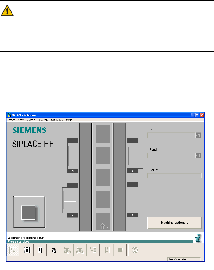
Fig. 4.1 - 2 Main view after loading the station computer software
4 Switching the SIPLACE line on and off SIPLACE Software Guide SR.504.xx
4.1 Switching on the SIPLACE line Issue 01/03 EN
52
NOTE
The current state of the station is displayed in the status field in the "Status“ line, and the action
you are to execute is displayed in the "Action:“ line (see Fig. 4.1 - 2). 4
Å When the "Press start button“ prompt appears, press one of the start buttons.
(The start buttons are located on the input side, output side and on the control panels on the
left and right sides of the station - HS-50 only.)
A reference run is executed on all axes. The station is ready for operation after the reference
run has been completed.
The symbol is displayed in the work area of the user interface.
4
4
4.1.4 "Switching on the SIPLACE line" flow chart
The following flow chart shows the actions executed while the SIPLACE line is being switched on
and started up. 4