00193697-01.pdf - 第18页
3 Graphical user int erface SIPLACE Softw are Guide SR.504.xx 3.2 Components of the user interface Issue 01/03 EN 18 3 Continue pr ocessing 3 The mac hine is s topped . 3 Click the bu tton: T he machi ne will con tinue p…

SIPLACE Software Guide SR.504.xx 3 Graphical user interface
Issue 01/03 EN 3.2 Components of the user interface
17
3.2.1 Icons in the working or display area
In main view, certain operating statuses (processing, error etc.) are indicated by different icons or
by changes in the color of the corresponding graphic in the display area. 3
Meaning of the Icons for the various different operating statuses 3
Machine power-up and reference run 3
When this icon is displayed, the majority of the functions of the machine cannot be operated. The
software is being loaded. Then the status field displays the status "Waiting for reference run" and
the action "Press start key". 3
Å Press the start key. The reference run is then performed.
After the reference run, the machine is ready to perform placement operations.
The following icon is then displayed.
3
Stop processing PCB 3
The machine is already running or is ready. 3
Click the button: The machine stops.
The icon changes to one shown below. This icon is then displayed until assembly of the PCBs in
the machine has been completed and these have been transported into the intermediate or output
conveyor, or in other words, until the processing conveyors have been emptied.
3
Shown after "Stop processing PCB" and while waiting for the processing
conveyors to be emptied 3
The machine is still placing components, but the stop button has already been activated. 3
Placement of the boards in processing conveyor 1 and 2 or the center conveyor will be completed
and these will be moved to the immediate or output conveyor. The machine will then be stopped.3
Click the button: The machine will continue without interruption. 3
(The triangle in the icon is continuously circled by a small yellow arrow.)
Once the processing areas have been emptied, the following icon is displayed. 3
3
3
3 Graphical user interface SIPLACE Software Guide SR.504.xx
3.2 Components of the user interface Issue 01/03 EN
18
3
Continue processing 3
The machine is stopped. 3
Click the button: The machine will continue placement. 3
This icon is displayed after "Stop processing PCB" or after a machine stop.
(The triangles in the icon move continuously from left to right.)
Click this icon to continue the interrupted operation once the error has been successfully
eliminated. 3
3
Å Click the icon.
Processing is now continued.
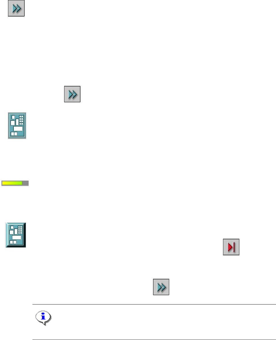
Processing PCB 3
The PCB has been taken up by the system and is being processed. The PCB icon is blue-green
in color. 3
3
Progress bar: 3
The Main view shows the progress of placement for each board being assembled in a given pro-
cessing area. The specification refers only to the current processing area and not placement of
the entire board. 3
Processing of PCB stopped 3
If processing of the PCB has been interrupted using "Stop processing PCB" or by an error
which caused a machine standstill or interrupted as a result of the Stop button being pressed, the
PCB icon is again displayed as a button and is blue-green in color.
3
Processing can be continued by clicking on the icon. 3
NOTE
The procedure used to abort processing is described below. 3
SIPLACE Software Guide SR.504.xx 3 Graphical user interface
Issue 01/03 EN 3.2 Components of the user interface
19
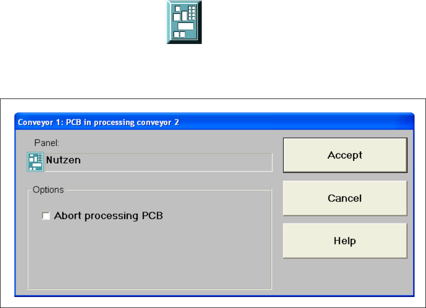
Abort processing PCB 3
3
Å Click the corresponding PCB icon .
If the PCB is located on the processing conveyor, the following dialog box is opened.
3
Fig. 3.2 - 2 "Conveyor 1: PCB in processing conveyor 1" dialog
Å Click the checkbox "Abort processing PCB".
Å Click the Accept button.
Processing of the PCB is aborted.
The incompletely assembled PCB is transported to the output conveyor and the operator is re-
quested to remove it by hand.