00193697-01.pdf - 第24页
3 Graphical user int erface SIPLACE Softw are Guide SR.504.xx 3.3 User interf ace - views and menus Issue 01/03 EN 24 3.3 User in terface - views an d menus 3.3.1 V iews T o perform a speci fic op eration vi a the user i…
SIPLACE Software Guide SR.504.xx 3 Graphical user interface
Issue 01/03 EN 3.2 Components of the user interface
23
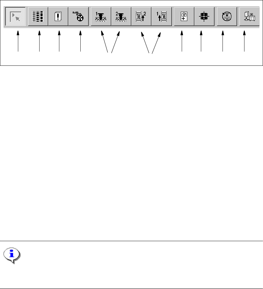
3.2.2 Toolbar in Main view
3
Fig. 3.2 - 4 Toolbar in Main view
3
Key to Fig. 3.2 - 4
(1) Main view
(2) Set-up, placement functions
(3) Error, placement functions
(4) Component feeder, placement functions
(5) Gantry 1 and 2, single functions
(6) Conveyor 1 and 2, single functions
(7) Teach fiducials, vision functions
(8) Test component, vision functions
(9) Start SITEST test program
(10) GEM Interface
3
NOTES for points (6) and (10) above
The single functions for conveyor 2 can only be called if a dual conveyor system has been config-
ured. 3
Å Click the required button in the toolbar.
This switches the user interface to the appropriate view.
The button corresponding to the view which is currently active itself becomes inactive.
3
1 8 9 10765432

3 Graphical user interface SIPLACE Software Guide SR.504.xx
3.3 User interface - views and menus Issue 01/03 EN
24
3.3 User interface - views and menus
3.3.1 Views
To perform a specific operation via the user interface, you may need to switch this to a different
view. You can do this by clicking the appropriate button on the toolbar (see section 3.2.2) or by
selecting the corresponding menu item from the "View" menu (see section 3.3.2.2). 3
3.3.2 Menus
3.3.2.1 "Mode" menu
The complete set of functions present in the "Mode" menu is only available in the main view.
In the views "Setup", "Errors" and "Feeders" and their sub-views, only the menu items "Stop pro-
cessing PCB" and "Processing PCB" are available. In the other views, the "Mode" menu is not
displayed. 3
NOTE
For a detailed description of the menu items "Stop processing PCB", "Processing PCB" and "Con-
tinue processing", refer to section 3.2.1 since these functions are usually activated via the corre-
sponding icons in the working area. 3

SIPLACE Software Guide SR.504.xx 3 Graphical user interface
Issue 01/03 EN 3.3 User interface - views and menus
25
3
3
Processing PCB 3
Assembly of the PCBs is started or continued if previously interrupted. 3
Å Click the Processing PCB menu item (or the corresponding icon).
3
Stop processing PCB 3
The current PCB assembly process is stopped. 3
Å Click the Stop processing PCB menu item (or the corresponding icon)
Abort processing 3
This function allows you to abort certain operating steps such as feeder position recognition or
nozzle changes in the event of a machine stoppage (due to fatal error, or if the Stop button being
pressed). 3
Å Click the Abort processing menu item.
The current operation is aborted when you confirm the action in the displayed dialog box.
Continue processing 3
The assembly process, which is interrupted, for example, as a result of an error, is continued once
the cause of the error has been eliminated. 3
Å Click the Continue processing menu item (or the corresponding icon).