00193697-01.pdf - 第19页
SIPLACE S oftware Guide SR.504.xx 3 Graphical user interface Issue 01/03 E N 3.2 Components of t he user in terface 19 Abort processi ng PCB 3 3 Å Cl ick t he corres pondi ng PCB ic on . If the PC B is lo cated on the pr…
3 Graphical user interface SIPLACE Software Guide SR.504.xx
3.2 Components of the user interface Issue 01/03 EN
18
3
Continue processing 3
The machine is stopped. 3
Click the button: The machine will continue placement. 3
This icon is displayed after "Stop processing PCB" or after a machine stop.
(The triangles in the icon move continuously from left to right.)
Click this icon to continue the interrupted operation once the error has been successfully
eliminated. 3
3
Å Click the icon.
Processing is now continued.
Processing PCB 3
The PCB has been taken up by the system and is being processed. The PCB icon is blue-green
in color. 3
3
Progress bar: 3
The Main view shows the progress of placement for each board being assembled in a given pro-
cessing area. The specification refers only to the current processing area and not placement of
the entire board. 3
Processing of PCB stopped 3
If processing of the PCB has been interrupted using "Stop processing PCB" or by an error
which caused a machine standstill or interrupted as a result of the Stop button being pressed, the
PCB icon is again displayed as a button and is blue-green in color.
3
Processing can be continued by clicking on the icon. 3
NOTE
The procedure used to abort processing is described below. 3
SIPLACE Software Guide SR.504.xx 3 Graphical user interface
Issue 01/03 EN 3.2 Components of the user interface
19
Abort processing PCB 3
3
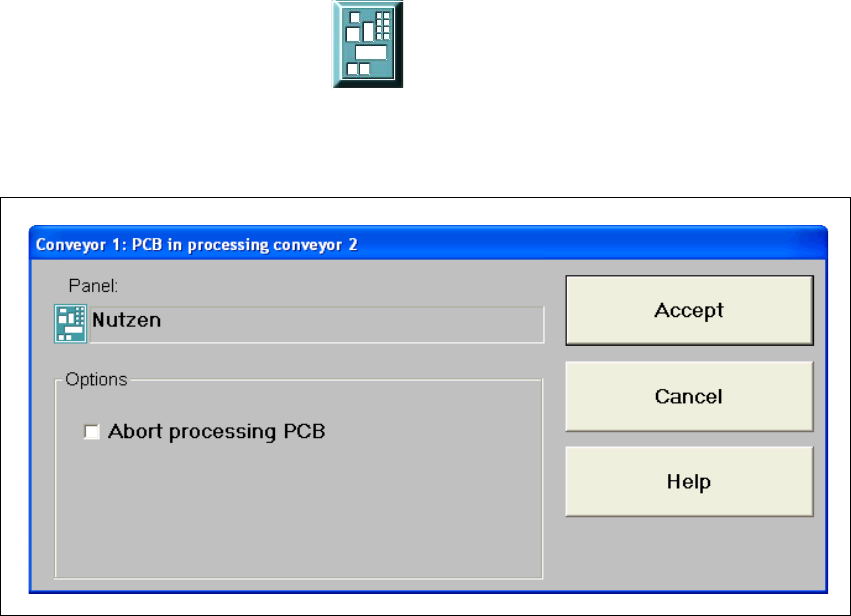
Å Click the corresponding PCB icon .
If the PCB is located on the processing conveyor, the following dialog box is opened.
3
Fig. 3.2 - 2 "Conveyor 1: PCB in processing conveyor 1" dialog
Å Click the checkbox "Abort processing PCB".
Å Click the Accept button.
Processing of the PCB is aborted.
The incompletely assembled PCB is transported to the output conveyor and the operator is re-
quested to remove it by hand.
3 Graphical user interface SIPLACE Software Guide SR.504.xx
3.2 Components of the user interface Issue 01/03 EN
20
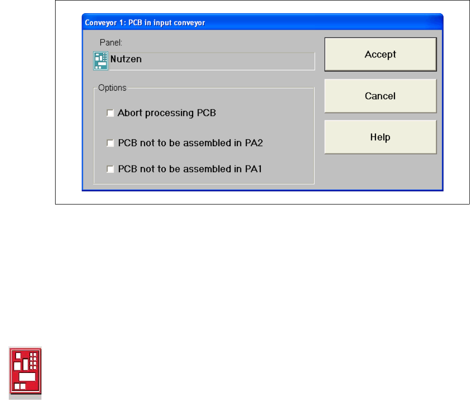
If the PCB is located on the input conveyor, the following dialog box is opened. 3
3
Fig. 3.2 - 3 "Conveyor 1: PCB in input conveyor" dialog
3
Å Click the checkbox "Abort processing PCB".
Å Click the Accept button.
Processing of the PCB is aborted.
The printed circuit board that has not been processed in this machine is transported onto the
output conveyor, and the operator is prompted to remove the board manually
Processing of PCB aborted 3
If processing of the PCB has been aborted by clicking the PCB icon (see example above), the
color of the PCB icon changes to red.
The icon is also displayed in red if a PCB is manually placed on processing conveyor 1 or 2. The
PCB is thus not recognized by the system and is transported to the output conveyor. 3