00191374-04.pdf - 第100页
6 Gantries Adjust men t Ins tru ct ion s SIPL ACE H S-50 6.1 Track Si gnals Edition 12/00 100 $QD ORJ7 UDFN6LJQDOV *D QWU\$[HV 0 HDVXUHPHQW6HWXSRI$QDO RJ7 UDFN6LJQDOV 2VFL OORVFRSH 6HWW…

Adjustment Instructions SIPLACE HS-50 6 Gantries
Edition 12/00 6.1 Track Signals
99
*DQWULHV
7UDFN6LJQDOV
7HVW(TXLSPHQW
1 dual channel oscilloscope > 20 MHz
– 1 track signal tester HS-50.
– Plastic feeler gauge 0.4 mm
2YHUYLHZ
$[HV 6HWWLQJ 2VFLOORVFRSH'LVSOD\
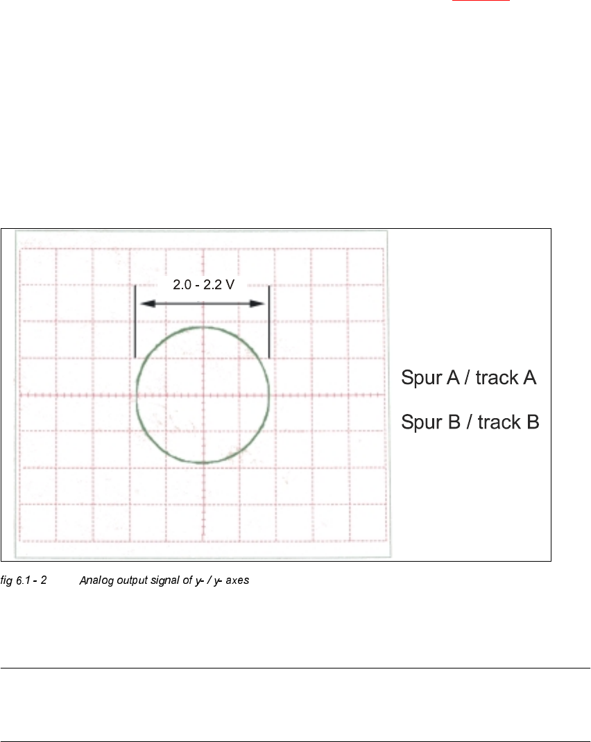
X read head adjusted to
0.4 mm,
parallel to scale
analog track signals:
digital track signal:
circuit with 1.8 V
diameter
pulse signals with
3.6 V
ss
and
90° degree phase
offset
Y read head adjusted to
0.4 mm,
parallel to scale
analog track signals:
digital track signal:
circuit with 1.8 V
diameter
pulse signals with
3.6 V
ss
and
90° degree phase
offset
6 Gantries Adjustment Instructions SIPLACE HS-50
6.1 Track Signals Edition 12/00
100
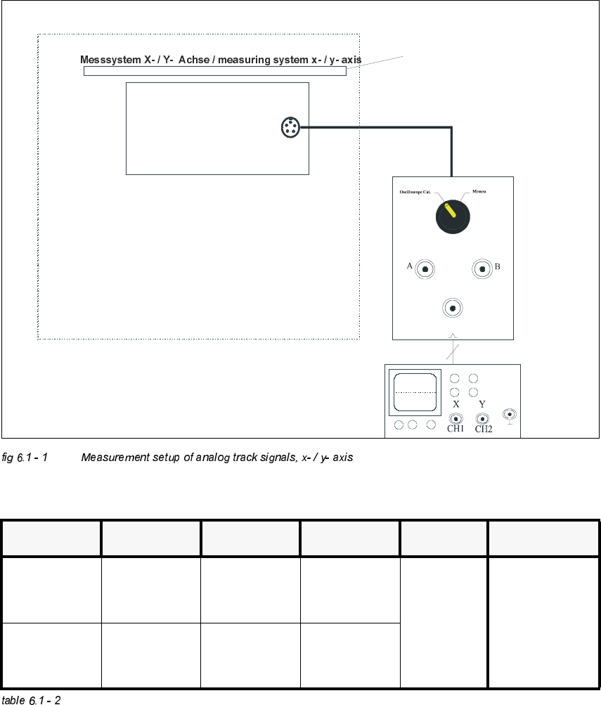
$QDORJ7UDFN6LJQDOV*DQWU\$[HV
0HDVXUHPHQW6HWXSRI$QDORJ7UDFN6LJQDOV
2VFLOORVFRSH6HWWLQJV
Inkrementalgeber X- / Y- Achse /
incremental encoder x- / y- axis
SIPLACE HS-50
Auflösung des Maßstabes: 1 Digit = 1 m
measuring scale: 1 dgt = 1 m
µ
µ
Spursignal - Tester /
track signal tester
BNC - Leitung
BNC line
track
zero pulse
analog
&KDQQHO 6LJQDO &RXSOLQJ <'HIOHFWLRQ 7ULJJHU ;'HIOHFWLRQ
CH 1
track A of
track signal
tester
DC 0.5 V/ DIV
x- / y- mode
auto 5 ms/ DIV
CH 2
track B of
track signal
tester
DC 0.5 V/ DIV
x- / y- mode
Adjustment Instructions SIPLACE HS-50 6 Gantries
Edition 12/00 6.1 Track Signals
101
3URFHGXUH
Å Turn on the machine.
Å Relate your measurement setup to the x-, or y- axis respectively. (See fig 6.5 - 3).
Å Adjust the oscilloscope.
Å Set the track signal tester to the "Oscilloscope cal" position.
Å With the help of the positioning switches CH1 and CH2, move the light spot exactly to the
center of the crosshairs of the screen.
Å Set the track signal tester to the "signal output" position.
Å Manually, move the appropriate axis (x = head / y = gantry) back and forth.
– If you adjusted the read head correctly, the following illustration will appear on the screen of
the oscilloscope:
$QDORJH=HUR3XOVHRIWKH*DQWU\$[HV
NOTE
The pulse width of the analog zero pulse is dependent on the speed at which the axis is
traversed.