00191374-04.pdf - 第108页
6 Gantries Adjust men t Ins tru ct ion s SIPL ACE H S-50 6.2 Zero Point Corrections Edition 12/00 108 =HUR3R LQW&RUUHFWLR QV Settin g of the zer o poi nt correc tions wi ll be d etermine d with m achine c alibr…
Adjustment Instructions SIPLACE HS-50 6 Gantries
Edition 12/00 6.1 Track Signals
107
Å With the help of the positioning switch CH2, move the light spot of the oscilloscope exactly to
the lower edge of the screen.
Å Swap CH1 to connector X11, or X24 respectively, to pin 2.
Å Swap CH2 to connector X11, or X24 respectively, to pin 5.
Å Manually, move the appropriate axis back and forth.
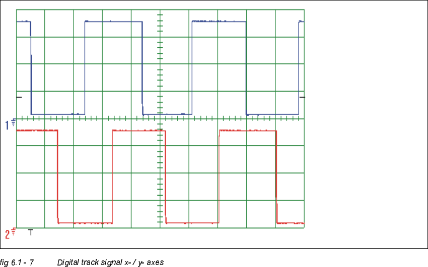
– If you adjusted read head correctly, the following illustration will appear on the screen of the
oscilloscope:
Spur A / track A
Spur B / track B
6 Gantries Adjustment Instructions SIPLACE HS-50
6.2 Zero Point Corrections Edition 12/00
108
=HUR3RLQW&RUUHFWLRQV
Setting of the zero point corrections will be determined with machine calibration.
Compare the chapter "Zero Point Calibration of Machine" .
Adjustment Instructions SIPLACE HS-50 6 Gantries
Edition 12/00 6.3 Mechanical Settings
109
0HFKDQLFDO6HWWLQJV
%HOW7HQVLRQRI;$[LV
0HDVXULQJ'DWDDQG$LGLQJ7RROV
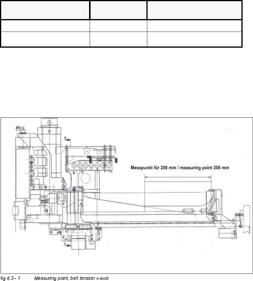
0HDVXULQJ6HTXHQFH
Å Move the x-slide against the stop on the motor side.
Å Measure the belt tension on the side of the placement head.
Å Center the measuring pin of the belt tension measuring device, 208 mm away from the
deflection pulley of the open ended toothed belt, as close as possible to the belt.
%HOW%UDQGQHZ %HOW6KUXQNDIWHUDSSUR[
KRXUVRIRSHUDWLRQ
toothed belt to be measured frequency (Hz) frequency (Hz)
at the x-axis (open ended) 53 Hz +1 / -3 Hz 53 Hz +1 / -3 Hz