00191374-04.pdf - 第159页
Adjustment I nstructions SIP LACE HS-50 7 Collect & Place Head DLM1 Edition 12/00 7.4 Dynamic Ad justment of the A xes 159
7 Collect & Place Head DLM1 Adjustment Instructions SIPLACE HS-50
7.4 Dynamic Adjustment of the Axes Edition 12/00
158
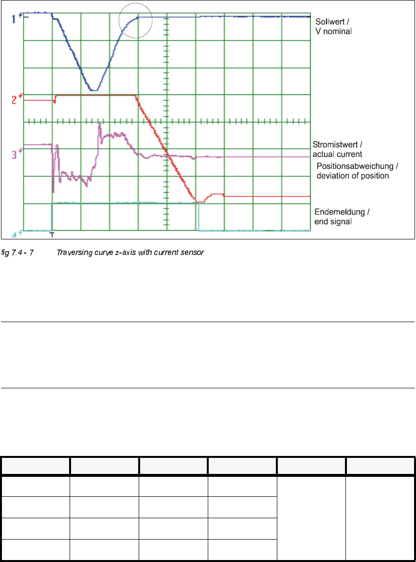
Å Increase the P-gain until an acceptable positioning of the axis becomes possible. Acceptable
means that a clear rounding at the rising edge of the nominal value has formed during transi-
tion to position control.
NOTE
Any oscillation of the current curve must be avoided.
Vnominal must be visibly rounded in the marked area.
(See marked circle in the illustration above).
Å If you adjusted the p-gain, proceed to repeat the adjustment of the tacho (see 7.4.5).
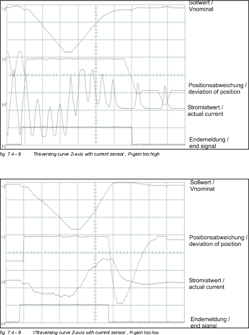
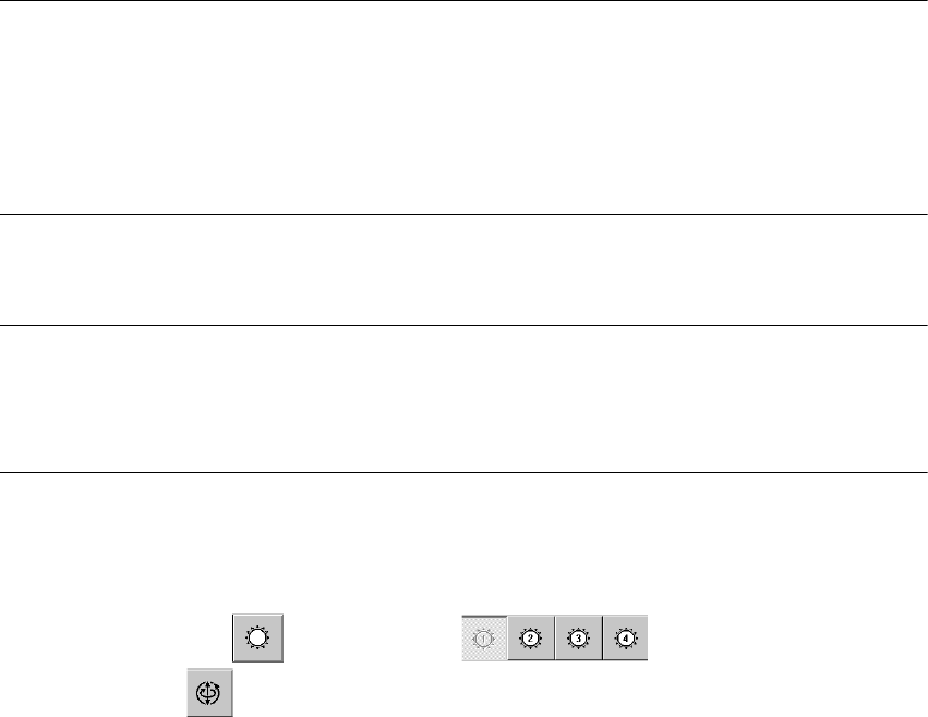
Å Control of P-Gain with Light Barrier ModeOscilloscope Settings
1. Setup oscilloscop, see fig 7.4 - 8 and fig 7.4 - 9
&KDQQHO 6LJQDO &RXSOLQJ <'HIOHFWLRQ 7ULJJHU ;'HIOHFWLRQ
CH1 Vnominal DC 2.0 V/ Div
CH 1
negative
10% pre
5 ms/ Div
CH2 deviat. of pos. DC 1.0 V/ Div
CH3 actual value DC 2.0 V/ Div
Ch4 end signal DC 5.0 V/ Div
Adjustment Instructions SIPLACE HS-50 7 Collect & Place Head DLM1
Edition 12/00 7.4 Dynamic Adjustment of the Axes
159
7 Collect & Place Head DLM1 Adjustment Instructions SIPLACE HS-50
7.4 Dynamic Adjustment of the Axes Edition 12/00
160
'S$[LV
*HQHUDO3UHSDUDWLRQV
Å Start SITEST.
Å Turn on the compressed air supply.
Å Prepare the measurement setup for the star-axis acoording to fig 7.4 - 4.
Å Set the oscilloscope according to the table below.
Å Perform a head reference run.
NOTE
Use an RC - filter to record the current curve
In order to measure the actual current on the servo amplifier, connect only the actual current and
no *1'.
Measure the end signal on the measuring adapter of the axis control card, with the switch
activated.
(IIHFWVRI3*DLQ6HW7RR+LJKRU7RR/RZ
NOTE
If the P-gain is set too low, the deviation of position will sag and the end signal will be prolonged.
If the actual current is set too high, the end signal will be prolonged as well, the actual current and
the deviation of position will oscillate however.
$GMXVWPHQWRI7DFKRWR9
6,7(67
Å Select "C&P Heads" ==> "Select head ==>
"Axis functions" ==> "Select dp - axis" ==> "Tacho adjustment".
Å Use the potentiometer "Tacho" on the servo board to adjust the displayed value on the station
monitor to 0V +/- 10 mV.