00191374-04.pdf - 第178页
178 9 Calibration of SI PLACE HS-50 (incl. SITES T version 501.xx ) Adjustment Instructions S IPLACE HS-50 9.9 Calibration of the C omponent Table Softwareversion SR.501.xx Edition 12/00 NOTE Make sure tha t the c al…
Adjustment Instructions SIPLACE HS-50 9 Calibration of SIPLACE HS-50 (incl. SITEST version 501.xx)
Softwareversion SR.501.xx Edition 12/00 9.8 Measuring the Fixed PCB corner
177
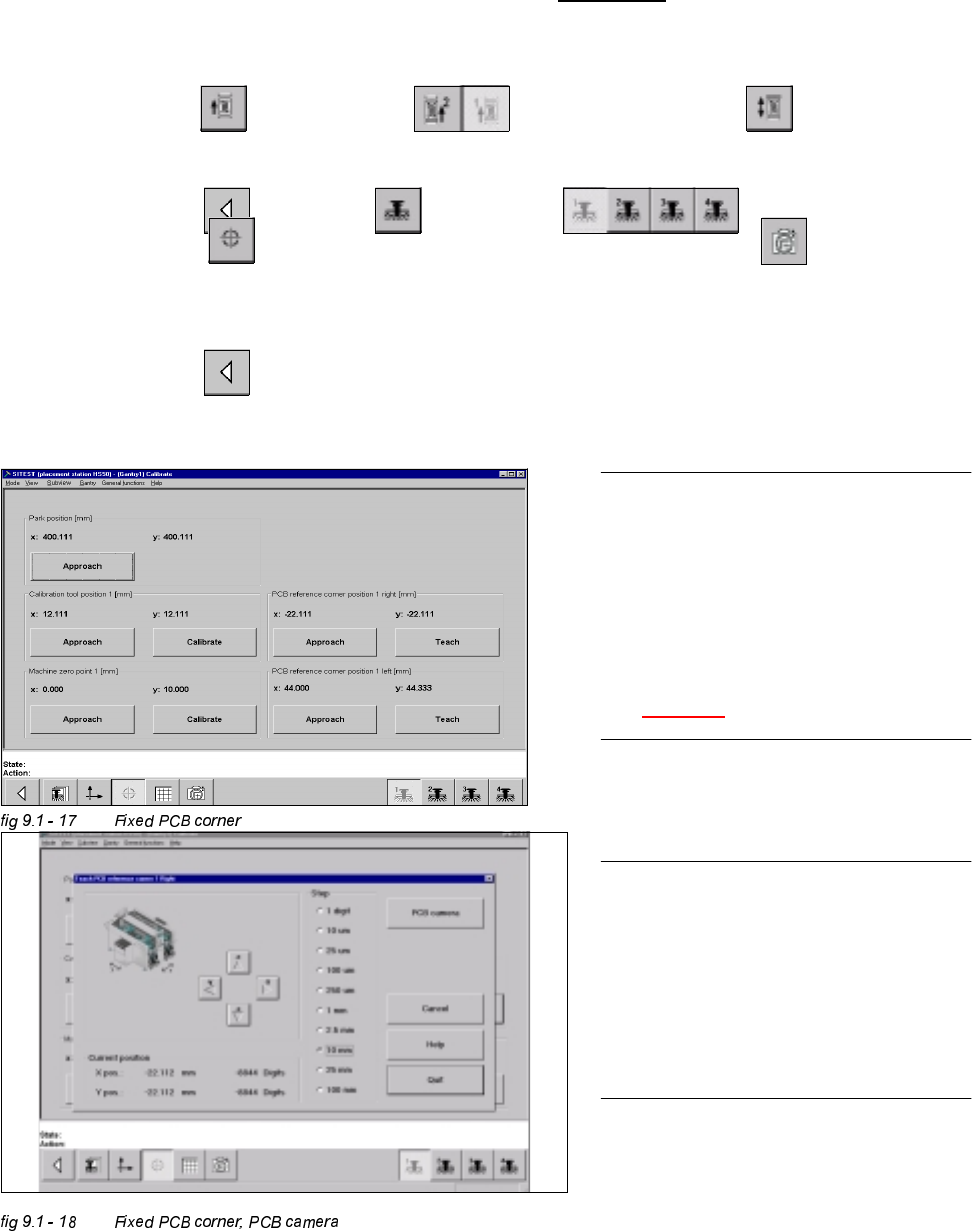
0HDVXULQJWKH)L[HG3&%FRUQHU
Example: Placement area 1 , conveyor of the right hand side (conveyor 1).
Å With the help of the conveyor functions, move a PCB with a light surface into the processing conveyor 1, in
which you wish to measure the position of the fixed PCB corner.
6,7(67
Å Select "Conveyor" ==> "Conveyor 1" ==> "Conveyor functions" .
Å With the help of the conveyor functions, move the PCB into placement area 1.
Å Select "Main view" ==> "Gantry" ==> "Gantry 1" ==>
"Calibrate position" ==> "Teach (field 1, right hand side)" ==> "PCB camera" .
With the help of the cursor buttons, teach the position of the fixed PCB corner.
Å Select ESC accept the position with "End".
Å Select "Main view" ==> "Save machine data".
NOTE
Make sure that the calibration data for the
PCB camera, the segment offset II (C&P -
PCB camera offset) and the machine zero
point have been determined already.
The position of the fixed PCB corners
varies according to conveyor model.
See fig 9.1 - 1.
NOTE
To measure the placement position in
placement area 2, follow the instructions
as detailed above, for gantry 2 as well.
If a dual conveyor is installed, the fixed
PCB corners of the left hand conveyor
(conveyor 2) must be measured as well.
178
9 Calibration of SIPLACE HS-50 (incl. SITEST version 501.xx) Adjustment Instructions SIPLACE HS-50
9.9 Calibration of the Component Table Softwareversion SR.501.xx Edition 12/00
NOTE
Make sure that the calibration data for the
PCB camera, the segment offset II (C&P -
PCB camera offset) and the machine zero
point have been determined already.
Before you use the gauge, make sure that
the appropriate component table under
the gauge is free of unevenness and dirt.
NOTE
Measuring the component tables 2, 3 and
4, proceed the same way.
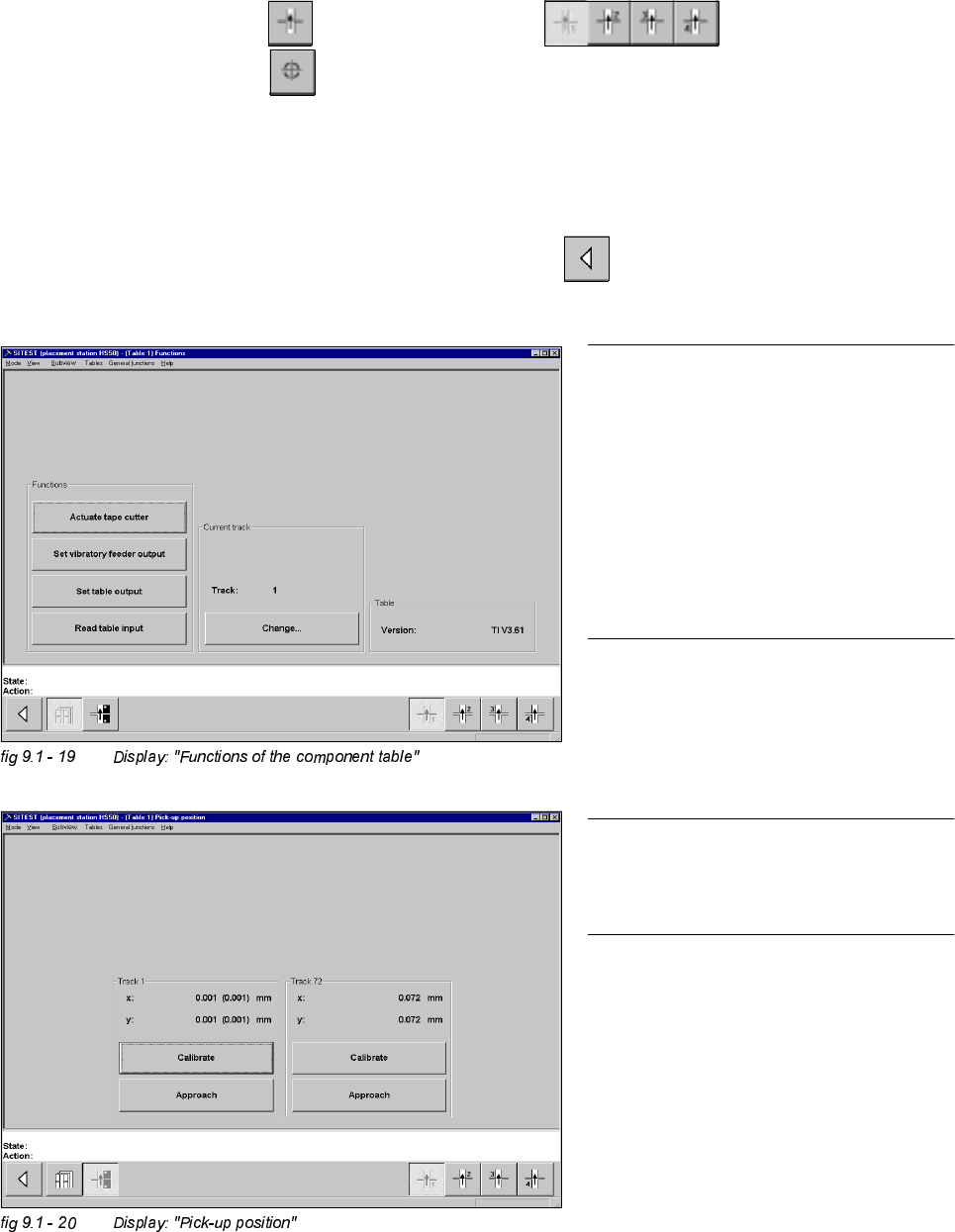
&DOLEUDWLRQRIWKH&RPSRQHQW7DEOH
Example: Component table 1
6,7(67
Å Select "Component tables" ==> "Component table 1" ==>
"Calibrate pick-up position" .
Å Set the gauge to track1 of the component table 1.
Å Select "Calibrate (field "track1") ==> "OK".
Å Set the gauge to track 72 of the component table 1.
Å Select "Calibrate (field "track 72") ==> "OK" ==> "Main View" ==>
"Save machine data".
Adjustment Instructions SIPLACE HS-50 9 Calibration of SIPLACE HS-50 (incl. SITEST version 501.xx)
Softwareversion SR.501.xx Edition 12/00 9.10 Determination of Traversing Paths of Gantry Axes
179
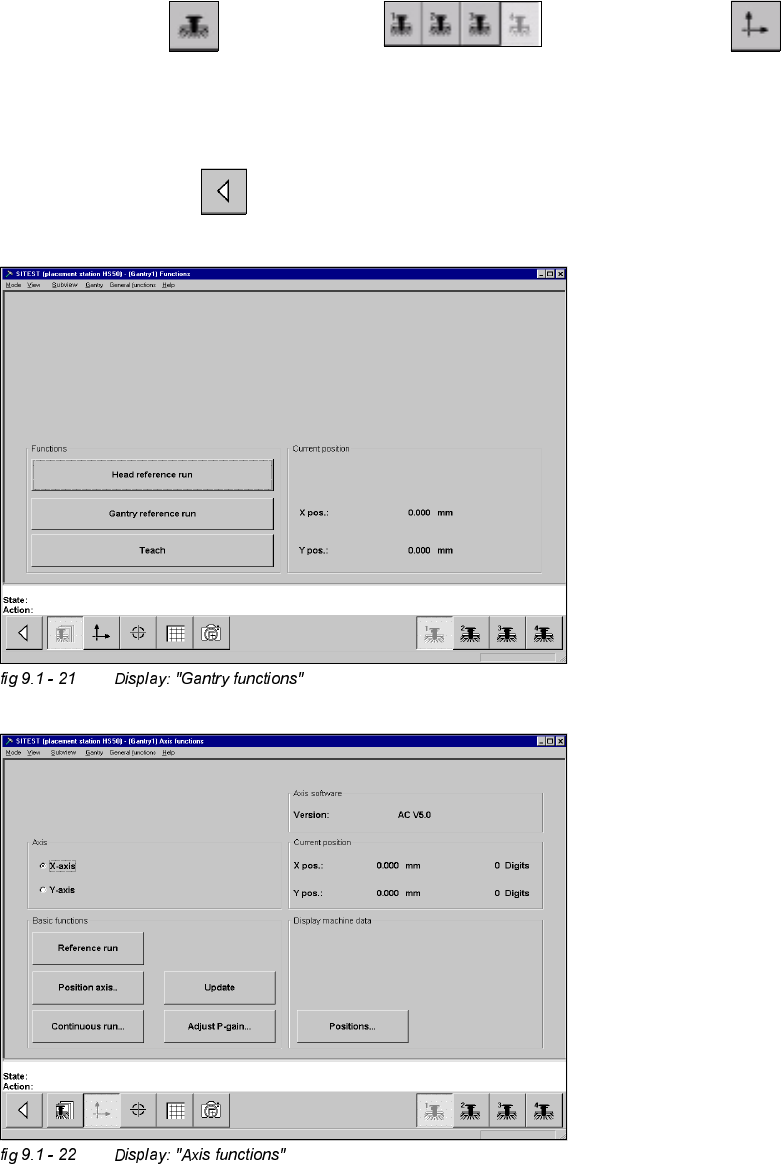
'HWHUPLQDWLRQRI7UDYHUVLQJ3DWKVRI*DQWU\$[HV
0D[LPXP7UDYHUVLQJ3DWK<$[LV*DQWU\
Å Manually, move the gantry 4 (3) up to 35 mm to the left hand machine stop.
6,7(67
Å Select "Gantry" ==> "Gantry 4 (3) ==> "Axis functions" ==> "Y-axis" ==>
"Positions...".
Å Edit the value for the current position of the y-axis under "Maximum position [dgts]" and
accept.
Å Perform a reference run.
Å Select "Main View" ==> "Save machine data".