00191374-04.pdf - 第39页
Adjus t ment In str uc tio ns SI PLA CE HS- 50 2 Operational Safety Edition 12/00 2.2 Safety Equipm ent 39 *XDUGRQWK H&RPSRQHQW7 DEOH/RFDWLRQV DANGER All loc ations m ust be equ ipped with fee ders in orde…
2 Operational Safety Adjustment Instructions SIPLACE HS-50
2.2 Safety Equipment Edition 12/00
38
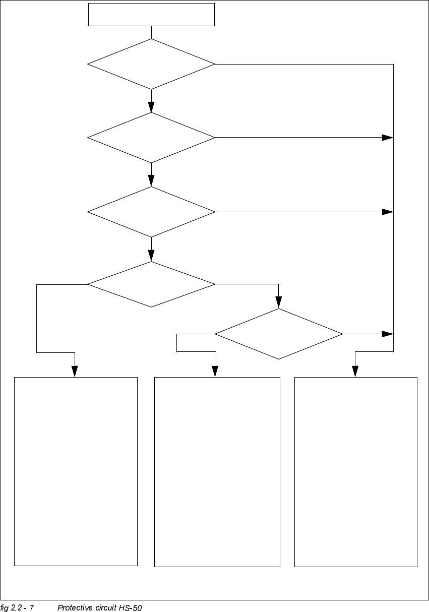
Compressed air
min. 5.0 bar?
No
START - button pressed
EMERGENCY STOP button
pressed?
Protective cover open?
Key switch
closed (Position I)?
No
Component table safety circuit
interrupted?
Yes
No
No
Yes
Yes
No
$FWLYH
PCC*) Yes
9ROWD J H
Y-axis 200 V
X-axis 200 V
Star-axis 100 V
Dp-axis 30 V
Z-axis 30 V
$FWLYH
PCB conveyor Yes
PCB clamping Yes
Width adjustment Yes
PCB stopper Yes
Lifting table Yes
Tape cutting unit Yes
Yes
$FWLYH
PCC*) No
9R O WDJH
Y-axis 0 V
X-axis 0 V
Star-axis 6 V
Dp-axis 30 V
Z-axis 30 V
$FWLYH
PCB conveyor Yes
PCB clamping No
Width adjustment Yes
PCB stopper No
Lifting table No
Tape cutting unit No
$FWLYH
PCC*) No
9ROWD J H
Y-axis 0 V
X-axis 0 V
Star-axis 10 V
Dp-axis 30 V
Z-axis 30 V
$FWLYH
PCB conveyor No
PCB clamping No
Width adjustment No
PCB stopper No
Lifting table No
Tape cutting unit No
*) PCC protective contactor combination
Yes
Adjustment Instructions SIPLACE HS-50 2 Operational Safety
Edition 12/00 2.2 Safety Equipment
39
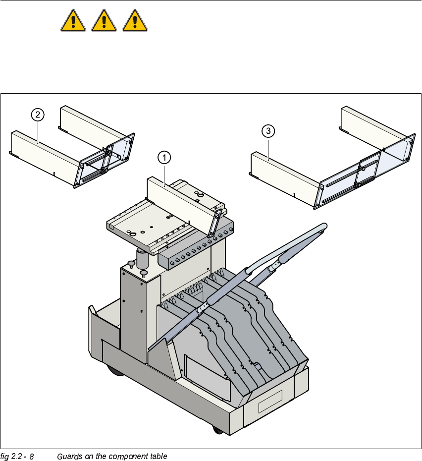
*XDUGRQWKH&RPSRQHQW7DEOH/RFDWLRQV
DANGER
All locations must be equipped with feeders in order to guarantee operational reliability. If there
are not enough feeders available, a guard ("feeder dummy") must be fitted in place of the feeder.
The following variants can be used:
.(<
(1) Guard for 1 location
(2) Guards for 6 - 10 locations
(3) Guards for 11 - 20 locations
2 Operational Safety Adjustment Instructions SIPLACE HS-50
2.2 Safety Equipment Edition 12/00
40
The following variants may be used:
Item no 00116820-01 SIPLACE guard for 1 location
Item no 00116821-01 SIPLACE guards for 6 - 10 locations
Item no 00116822-01 SIPLACE guards for 11 - 20 locations